Search This Blog

Saturday, January 30, 2016

Lap winding; Simplex and Duplex Lap Winding


In small DC machines the coils are directly wound in the armature slots. In large DC machines, the coils are performed and then inserted into the armature slots. Each coil consists of a number of turns of wire, each turn taped and insulated from the other turns and form the rotor slots.

Each side of the turn is called the conductor. The number of the conductors on a machine's armature is given by

                                      Z= 2CN
where :
Z= numbers of conductors on rotor
C= numbers of coils on rotor
N= number of turns per coil


There are two types of armature windings in DC motors :-
1.  Lap winding
2.  Wave winding.
In this article we will discuss about Lap winding:-

Lap Winding:-
In this winding continuous coils overlap each other. In this winding finishing end of one coil is connected to the one commutator segment and starting end of next coil situated under same pole and connected with same commutator segment.

In Lap winding number of parallel paths are equal to number of poles.
In Lap winding also number of brushes equal to number of poles.
When two adjacent commutator bars make contact with a brush, one coil is shorted by the brush in the lap winding.
Its name “Lap” comes from that it doubles or laps back with its succeeding coils. Lap winding is as shown below:-

Lap winding


From above we can see that finishing end of coil - 1 and starting end of coil - 2 are both connected to the commutator segment - 2 and both coils are under the same magnetic pole that is N pole here.

Lap Winding has two types:-
1.   Simplex Lap winding
2.   Duplex Lap winding

1.         Simplex Lap Winding
In one type known as Simplex Lap Winding the end of one coil is connected to the beginning of the next coil with two ends of each coil coming out at adjacent commutator segment. For a progressive lap winding the commutator pitch y = 1.  In this winding number of parallel path between the brushes is equal to the number of poles. Simplex lap winding is as shown below:-

Simplex Lap winding


2.           Duplex Lap Winding
In this winding number of parallel path between the brushes is twice the number of poles is called duplex lap winding.
There are few points which must be taken care before designing lap winding:-
Duplex lap winding


If,
Z = the number conductors
P = number of poles
YB = Back pitch
YF = Front pitch
YC = Commutator pitch
YA = Average pole pitch
YP = Pole pitch
YR = Resultant pitch

Then, the back and front pitches are of opposite sign and they cannot be equal.
YB = YF ± 2m
m = multiplicity of the winding.
m = 1 for Simplex Lap winding
m = 2 for Duplex Lap winding
When, YB > YF, it is called progressive winding.

YB < YF , it is called retrogressive winding.
Lap winding


Back pitch and front pitch must be odd.
Resultant pitch (YR) = YB - YF = 2m

YR is even because it is the difference between two odd numbers.

Average Pitch(YA)= YB+ YF
                                      2

Pole Pitch (Yp)= Z/P

Back Pitch (YB)= Z/P

Commutator pitch (YC) = ±m
Number of parallel path in the Lap winding = mP


Lap Winding Advantages:-

1.   As there are more parallel paths so this winding is used where there is requirement of large current.
2.   These windings are suitable for low voltage and high current applications
 Lap Winding Disadvantages:-

1. As this winding has low emf so no. of conductors required more for generating same emf as in wave winding. This will leads to higher cost

 2. This winding utilize lower space on armature so leading to less utilization of space.

Friday, January 29, 2016

V/f control in Induction Motors; Volts per Hertz control

V/f control of Induction motors
V/f control is also known as volts per Hertz control. This method is the simplest method for motor control.  In this control method there is not requirement of tuning . This type of control is used where there is requirement for operating the motor up-to 1000 HZ.

V/f control has some limitations that is weakness in starting torque and lack of control. By V/f method several motors can be started on single VFD which is not possible with encoder control. When several motors are connected on single VFD all motors can start and stop at same instant and also these motors will run same speed reference.
In V/f control method speed regulation is typically 2%-3%. Speed response in that type of control is 3 Hz. Speed response is how well the VFD responds to change in reference frequency.  If this speed response increases then this means that motor will response quicker with the reference frequency change.
VFD speed control range in V/f control is in the range 1:40 . If we multiply this range with maximum frequency then this will determines the VFD’s minimum running speed at which it can control the motor. Lets take an example if rated frequency is 50 HZ then speed control will be 1:40X50= 1.25Hz.
There are two types of loads Variable torque loads and constant torque loads.
Torque formula for induction motors is as below:-
 
Torque Speed Formula for Induction Motors

Torque speed characteristics for Induction Motors is as below:-
Torque Speed Characterisctics

From above characteristics you will see that X-axis shows speed and slip while the Y-axis shows Torque and Current. When the motor is started, it draws very large current 6-7 times the rated current during starting, torque is around 1.5 times the rated torque of motor. 

As motor speed increases current reduces slightly and then drops significantly when the speed reaches close to 80% of the rated speed. At the base speed, the rated current flows in the motor and rated torque is delivered.
At base speed, if the load is increased beyond the value for the rated torque, the speed drops and the slip increases. At a speed of 80% of the Synchronous speed, the load increases up to 2.5 times the rated torque, this is called the breakdown torque. Increasing the load further causes the torque to fall rapidly and the motor stalls


 A variable torque V/f control will prevents faults and increases performance and efficiency of motors. In this control magnetizing current  get reduced at low frequencies by lowering down the motor voltages at lower frequencies.
Torque speed curve for V/f control is as below:-
Torque Speed Characteristics V/f control

Now in constant torque applications need full magnetizing current at all speeds. So in this method straight slop is made and followed throughout the entire speed range.
There are various advantages of V/f control:-
(i)                            It provides wide range of speed.
(ii)                          This control will gives good running and Transient performance
(iii)                        Voltage and frequency reach rated value at base speed.
(iv)                        This is cheap and easy wiring
(v)                          This has low starting current requirements

Normal duty VFD Vs heavy duty VFD

There is thumb rule that Normal duty VFD’s are used for variable torque applications and Heavy duty VFD’s are used for constant torque applications.
This doesn’t imply that Normal duty VFD’s can’t be used for constant torque applications. Normal duty VFD’s can be used for Heavy duty applications but motor rating should be needed to be reduced, if there is VFD of 20 KW for normal duty than for heavy duty it will get reduced 15 KW.
In Normal duty VFD’s has specifications of overload for 110% for 60 Sec’s
And heavy duty VFD’s has specification of overload for 150% f0r 60 sec’s.
Normal duty VFD’s have higher continuous current rating than Heavy duty VFD’s.

Tuesday, January 26, 2016

Krichoff's current law and Kirchoff's voltage law

As we know that Ohm’s law can be applied to circuits where there are resistive circuits only.  Now in electrical systems there are so many complex circuits consisting of lot of other load other than resistive loads. There are some circuits such as Bridge circuits which can’t be solved by using ohm’s law to find out voltages and currents circulating in the circuit. Kirchoff’s current law is used to solve the circuits to find out the current flowing the respective branches.

Kirchoff’s current law was given by Gustav Kirchoff in 1845. There are two laws given by Kirchoff naming as Kirchoff’s current law and Kirchoff’s voltage laws. KCL deals with current flowing in a closed circuit whereas KVL deals with voltage sources present in a closed circuit.
Kirchoff’s Current Law:-
According to this law “Total current entering a Junction or node is equal to current leaving the same junction or node”.  This means that algebraic sum of currents entering and leaving the junction or node is always zero. Currents entering the particular node are represented by positive and currents leaving the junction or node are presented as negative.
Kirchoff’s current law is also knows as Conservation of charges.
In Figure below you will see that at a particular Junction or node; Sum of currents entering the node= Sum of currents leaving the node
In figure you will see that:-

I1+ I2+ I3= I4+I5+ I6
Kirchoff’s current law can be used for analysis of parallel circuits.
Kirchoff’s Voltage Law:-
According to this law “in a closed network the total voltage around the closed circuit is equal to sum of voltage drops within the same circuit.”
This means that algebraic sum of all voltages within the closed circuit is always equal to zero. This law is also known as  Conservation of Energy.
In figure below you will see that in a closed loop there is direction of voltage drop is positive at point V12 and V23 but –ve in V34 and V41. So sum of all voltages in circuit is zero. It should be kept in mind that direction should be either selected as clockwise or anticlockwise for whole circuit.


Kirchoff’s voltage law is used to analyze Series circuit.

Kirchhoff's rules can be used to analyze any circuit this can be modified for those with EMFs, resistors, capacitors and more


Friday, January 22, 2016

Star to Delta and Delta to Star conversions

We have seen Star and delta connection is Transformers. Now Star into delta conversions allows us to convert impedances connected together from one type of connections to another. This conversion can be done by using Kirchoff’s circuit laws.

Star to Delta Conversion
In three phase power supply Star to delta conversion can be done easily by using these transformations.
Circuit for the conversion is as shown below:-
Star to Delta Conversion

There are following formula used for conversion for Star to delta.

Resistance RA= R1R2 + R2R3 + R3R1        ……………… (i)
                                      R3
Resistance RB= R1R2 + R2R3 + R3R1   ……………… (ii)
                                      R2
Resistance RC= R1R2 + R2R3 + R3R1   ……………… (iii)
                                      R1

Delta to Star Conversion
Now you see from above formula when there is need to calculate equivalent resistance in delta connection while conversion from Star connections is sum of product of every two branch resistances in star connections divided by resistance if opposite branch. From equation (i) you see that while calculating resistance in delta across branch RA then this will be equal to sum of product of two branches divided by resistance of opposite node. Similarly resistance value of other branches can be calculated.

Diagram for conversion from Delta to Star is as below:-
Delta to Star conversion


Now let’s see when there is conversion from Delta to Star then following formula can be used:-
Resistance R1=     RA RB  ……………………………..(a)
`                         RA+RB+RC
Resistance R2=    RA RC    ……………………………..(b)
                           RA+RB+RC
Resistance R3=    RB RC    ……………………………..(c)
                           RA+RB+RC

Now from above we can see that while conversion from delta to star connections resistance of branch  which is under calculation is equal to product of two branches which are connected to Node divided by Sum of resistances of all branches .
From equation 1 we have seen that while calculating resistance across branch RA , resistance will be product of resistances connected to node1 while in delta divided by sum of resistances in all branches.

From above you can see that it will be easy to convert star into delta and delta into star by using these formula’s. This conversion is used to analyze the circuits. These transformations are applicable for both resistance and impedances.
These Transformations are used to solve complex circuits.


Saturday, January 9, 2016

Transformer Losses; Eddy current Hysteresis losses

Transformers are backbone of electrical systems. They are used for stepping up and stepping down the voltages.
We will study about losses in Transformer in this article. Losses are necessary evil in electrical systems. These losses can be minimized but could not be eliminated.
Transformers are static devices as they don’t have any rotary parts as these are static devices these don’t have any mechanical losses. Now there are only electrical losses which are needed to be looked upon.

There are various types of electrical losses in a Transformer, these are as below:-
1.    Core losses
2.    Copper losses


1.    Core losses:-
As clear from its name these losses occur in Transformers core and these consists of Hysteresis losses and eddy current losses. Hysteresis losses and eddy current losses both depends upon magnetic properties of Transformer core. These losses are always fixed and also known as no load losses and these don’t depend upon load current. These losses are also known as iron loss in Transformers.
Hysteresis Losses:-
How these losses are generated in Transformer is as explained below:-
Core of Transformer is made of CRGO Silicon Steel i.e. Cold rolled grain oriented Silicon Steel. As Steel is ferromagnetic material and ferromagnetic materials are very sensitive to magnetism. Now whenever magnetic flux passes through transformer core, core starts behaving like a magnet. As we know that magnetism is associated with domains. These domains are arranged in magnetic material in such a random manner so that resultant magnetic field of that material is zero. Whenever magnetic field is applied externally to that material these randomly oriented domains get aligned towards external mmf direction. When external mmf is removed maximum no. of domains come back to their random positions but till some domains still remains unchanged. To bring back these domains to their random position some external opposite mmf required to applied. The mmf applied to transformer to bring back domains in original position is alternating. This leads to electricity consumption and this is known as Hysteresis losses.

Eddy current losses:-
In Transformers power supply is applied to Transformer primary winding, this power supply which is alternating in nature produces alternating magnetic flux in the core, that flux links with secondary winding which will leads to induced voltage in secondary winding. Some of alternating flux also links with other parts of Transformer which are conducting in nature. These linkage fluxes will generate local induced EMF in these parts. This will leads to losses of energy as this will not contribute to Transformer output. So these losses are known as eddy current losses.

There are following formula uses to represent Hysteresis losses and eddy current losses:-

Hysteresis loss (Wh)= Kh X f X (Bm)1.6
Where Kh=Hysteresis Constant

These are measured in watts.
Now eddy current losses (We)= Ke X f2X K2fX(Bm)2
Where Ke= Eddy current constant
Kf= Form constant
From above relations we see that both Hysteresis losses and eddy current losses are independent of voltage and current. These losses are depend upon frequency and magnetic field strength as Hysteresis losses are directly proportional to system frequency and relation with magnetic field is as per equation.
Eddy current losses are proportional to square of both frequency and magnetic field strength.
2.    Copper losses:
Copper losses are the losses which occur in Transformer winding and these losses depend upon load current. These losses are also known as variable losses.
Copper losses are = I2R + Stray losses
Copper losses are also known Ohmic losses.


Friday, December 25, 2015

Full wave rectifier; Full wave bridge rectifier

Full Wave Rectifier:-
Full Wave Rectifier are used to convert AC into DC. Average DC output of full wave rectifier is more than half wave rectifier also ripples are lower in DC in full wave rectifier in comparison to half wave rectifier.

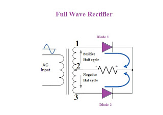
Full wave rectifier circuit consists of 2 no. of diodes one for each half cycle.
Full wave rectifier circuit is as shown below:-

Full wave rectifier

In above circuit secondary winding is center tapped. In this circuit each diode starts conducting when anode terminal is positive with respect to transformer center point. This will leads to conduct both diodes alternately and produces DC in both half cycles of AC.
In circuit shown above you can see that there are two diode connected to single resistive load.In Transformer when point 1 get positive with respect to center point 3 diode 1 starts conducting and direction of flow is shown as in figure.

Now when point 2 get positive with respect to center point 3 than diode 2 starts conducting in forward direction and direction of conduction is  as shown in figure. You can see that direction of flow of current through load that is R is same. As direction is same in Resistor this means it act as full wave rectifier.
Output waveform of Full wave rectifier is shown below:-


Full wave rectifier Output waveform


From Waveform we can see that there are 2 Vmax in every alternating current full cycle. From above we can get:-

Output Voltage of Full wave rectifier is= 2 Vmax  = 0.637 Vmax= 0.9 V rms
                                                                  Π
Where Vmax is the maximum peak value in one half of secondary winding
Vrms is the RMS value

There are some disadvantages associates with full wave rectifier one of the main disadvantages is that full wave rectifiers requires large rating transformer is required for given output which makes it very costly. To Overcome this problem full wave Bridge rectifier are used as this doesn’t require center tapping of transformer which will leads to reduction in cost and size of Transformer required.

Full wave Bridge Rectifier
There are four diodes used in this circuit and circuit diagram of full wave bridge rectifier is as shown below:-


Full wave Bridge Rectifier

There are four diodes connected to one load and 2 no.s diodes conduct in each half cycle. In the circuit diode 1 and 2 conduct in positive half cycle and 3 and 4 conduct in negative half cycle.

To minimize ripples in the output waveform smoothing capacitors are used at Output of the rectifier. This capacitor is used to smoothen the DC output . By connecting capacitor at rectifier output average DC output level will be increased.

Smoothing capacitor:-

Circuit diagram for the same is shown below with capacitor connected in circuit.

Full wave rectifier with Smoothing capacitor

The capacitor converts the rippled output of full wave rectifier to smooth DC output voltage. Capacitor used for smoothing DC output is usually of rating 100 microfarad. Capacitors used for this purpose are aluminum electrolytic type. Repeated DC voltage pulses from the rectifier charging up the capacitor to peak voltage.
While selecting capacitor of smoothing DC voltage following factors must be taken into consideration:-
(a)   Working voltage, working voltage should be higher than the no-load output value of rectifier
(b)   Capacitance value, this is used to determine the ripples which will superimpose on DC output voltage.
Capacitor value should be large enough to smoothen out the DC voltage as too low capacitance will have little effect on output voltage waveform.
Resultant waveform with Smoothing capacitor is as shown below:-

Full wave rectifier Output Waveform with smoothing capacitor

From above you will see how smoothing capacitor will increase DC output of full-wave bridge rectifier.