Search This Blog

Saturday, August 5, 2017

Working and functions of alternator in cars and starting current of cars

Alternator in Cars

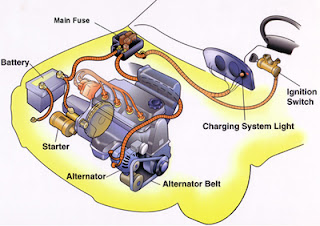
Alternators are used in cars to generate current for running of cars. We quite often get confused that why alternator is required when there is battery available in cars.

Battery in cars is only used for starting the cars, but for lights operation and functioning of other parts current is required now from where that power will come???
Working and functions of alternators in cars; Starting current of cars

For fulfilling the above purpose alternator is required, alternator has following functions in cars:-
(i)            Running of lights, heater, Air conditioners and operation of other electrical accessories
(ii)          Recharging of battery as it get discharged during starting.
Now how this alternator works in cars and who provides mechanical power to alternator so that power output can be generated at alternator output??
When you switched off your car engine than radio of car will work on car battery. For engines running following are required:-
(i)                    Air
(ii)                  Fuel
(iii)                 Spark
Last part is supplied by alternator because spark is generated through electricity,  although battery is available for supplying the spark but not for keep running the car. Battery electricity is sufficient for keep running the vehicle for few KMs  but vehicle required  much more than that , so to serve the purpose alternator will comes into picture.  Alternator in vehicle has output of 13.5 - 14.8 volts.
In past generators were used in cars, these generators are very inefficient in comparison to alternators, also at that time charging of battery and keeping accessories lighting up was different from present scenario. There are following components of alternators:-
(i)            Stator
(ii)          Rotor
(iii)         Voltage regulator you can also say automatic voltage regulator
(iv)         Direct current circuitry consisting of diodes
Now with rotation of rotor electricity get generated and output is used for charging batteries and keeping the auxiliaries ON.
DC circuitry is used to convert the alternating current generated by alternator to DC. Voltage regulator is used to keeping the voltage generated by alternator within limits.  Feedback is received by voltage regulator and accordingly output gets controlled.  Now day’s voltage regulators are integral part of alternators. But in past voltage regulators were big boxes and they were kept in hood and wired into the system. Voltage regulator functions are as below:-

(a)  Cut off the power to battery when battery get fully charged i.e. when battery voltage reached certain level around 14.0-14.5  volts
(b)  To keep voltage level within limits as per requirement of auxiliaries.

How to get noticed that Alternator is faulty??

It can be easily detected as you will observe reduced illumination from head lights , sometimes reduced illumination may not get detected while driving as during that time battery will provide necessary electricity . But as battery power get used for illumination of headlights now when you tried again to restart the vehicle then vehicle doesn’t start as battery get drained up.

Starting current of a car:-

When you tried to start a car your battery should be strong enough to provide crank to engines so that car get started easily. You may often see that very heavy leads are connected at battery terminals as starting current is very heavy for starting the car. By Ohms law we know that Voltage = Current X Resistance and now Voltage of battery is 12 V and starter motor resistance is approximately 0.12 Ohm so
Current = 12/ (0.12 + Internal resistance of battery)
Now lower is the resistance of battery higher will be the starting current. Now it is general practice that more expensive is the battery lower will be the resistance.
So higher will be the current and faster will be the starting of vehicle.
From above equation we will also find that if we neglect battery resistance then starting current will be 100A. So staring current will be also less than 100A always. If your battery is fully charged then it will be good enough to overcome the problem of poor internal resistance of battery. Battery is considered to be fully charged at 12.6 volt levels and low at 12.6 Volts and completely discharged at 11.9 Volts. Good quality batteries will able to start vehicle even when it is completely discharged so much but a poor quality battery may not be able to start vehicle even at 80% charged position.

In general when your car is new then you can buy any battery and don’t worry about anything but when your get older always buy a high quality battery, as resistance of older wires may get increased which may leads to lower starting current. So we have also seen that during starting current is very high approx. 100 A so it is always advisable to use strong leads capable of taking that 100A load.

Friday, July 28, 2017

Designing a plant; Reduction factors while laying cables in bunches and layers

There are following procedure to be adopted for correct dimensioning of a plant

(i)            Load Analysis:-
First step in dimensioning of a plant is to check for connected load and their location

Now check for location of power distribution panels
Now we can calculate cable requirement i.e. length of cables and path of cable laying
Now we will do calculations of total power consumption while taking account utilization factors and demand factors


(ii)          Transformer and generator size calculations:-
Transformer and generator size are usually selected 15-30% more in comparison to total connected load considering future prospectus.

(iii)         Conductor size selection-
Now we calculate cable size according to load requirement of various connected loads. Cable selected may be copper or aluminum. Cables selection must also consider voltage drop at load current under specific reference conditions.

(iv)         Selection of Protective circuit breaker:-
Short circuit calculations can be done and accordingly switchgear busbar and switchgear should be selected. It is always considered to select circuit breaker with breaking capacity higher than short circuit current. Rating of circuit breaker should be higher than rated current of load connected to circuit breaker. Characteristics of circuit breaker should be according to connected to load.

(v)          Protection of conductors:-
For protection against overload circuit breaker rating should be higher than the load current but should be lower than Rated current carrying capacity of conductor.
In case of short circuit protection circuit breaker setting should be lower than short circuit current withstand by conductor.

(vi)         Protection of Load:-
For protection of load such as motors which constitute 70% of total load of any industrial and commercial establishment overload relays and other protections must be provided after breaker so that tripping of relays leads to protection of load. For protection of human beings from electrical shocks it is always recommended to install RCCB or ELCB.


Selection of the cable
For installation and calculation of current carrying capacity of cables in Industrial, commercial and houses cable selection should be as per International standard IEC 60364-5-52 i.e. “Electrical installations of buildings Part 5-52 for “Selection and Erection of Electrical Equipment- Wiring systems”.

There are following ways and parameters are used to select the cable type:
a)    Conductivity of Material:-
The foremost parameters to be considered while selection of cables is conductivity of material. Copper is costlier then aluminum but selection depends upon cost of material, size of material , weight of material, resistivity of material and resistivity to corrosive environment. Generally copper is having higher current carrying capacity i.e. 30% higher than aluminum conductors for same cross-sectional area, this is due to fact that aluminum is having higher resistivity than copper i.e. 60% higher than copper conductor.

b)     Insulating Material used for conductors:-
There are so many insulating materials used for copper or aluminum conductors. Insulating material may or may not be used for conductors. Materials used for conductors may be PVC, XLPE. Insulating material will affects maximum temperature that a cable able to carry under normal and short circuit conditions.

c)     Type of conductor:-
            There are following types of conductors:-
a)    Bare conductor
b)    Single core cable without sheath
c)    Single core cable with sheath
d)    Multicore cable with sheath and armored
e)    Flexible multicore cable
Cable can be selected according to mechanical resistance, degree of insulation and difficulty of installation required by the method of installation.

Conductors reduction factor while laying the cables in different arrangement of laying the cables:-
It has been observed that with presence of other cables laid around the cable , cable current carrying capacity is influenced significantly. This happens because heat dissipation of single cable get affected due to presence of other cables nearby.
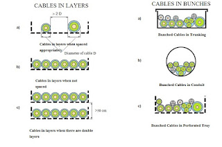
Cables in layers and bunches


Below we will discuss effect of other cables on current carrying capacity of single cable. For same there is factor K2 comes into picture according to installation of  cables laid close together in layers or bunches.

The value of correction factor K2= 1 when:
Distance between two single core cables of different circuits is more than twice that of external diameter of the cable with larger cross section.
Adjacent cables are loaded less than 30% of current carrying capacity.

The correction factors for cables which are either bunched or laid in layers is usually calculated by assuming that  all cables laid in bunches are similar cables and also load on cables is same. The calculation of the reduction factors for bunched cables with different crosssections depends on the number of cables and on their cross sections. These factors have not been tabled, but must be calculated for each bunch or layer.
The reduction factor for a group containing different cross sections of insulated conductors or cables in conduits, or cable ducting is:
where:


K2= 1/(n)1/2

• K2 is the group reduction factor;
• n is the number of circuits of the bunch.

The reduction factor obtained by this equation reduces the danger of overloading of cables with a smaller cross section, but may lead to under utilization of cables with a larger cross section.  Such under utilization can be avoided if large and small cables are not mixed in the same group.
The following tables show the reduction factor (k2).

Reduction Factor for grouped cables:-
Item
Arrangement (Cables Touching)
1
2
3
4
5
6
7
8
9
12
16
20
To be used with current- carrying capacities Reference
1
Bunched in air/ on a Surface/ enclosed
1.00
0.80
0.70
0.65
0.60
0.57
0.54
0.52
0.50
0.45
0.41
0.38
Method A to F
2
Single layer on wall, floor or flat tray
1.00
0.85
0.79
0.75
0.73
0.72
0.72
0.71
0.70
No further  reduction factor for more than  nine circuits or multicore cables
Method C
3
Single layer fixed directly under a wooden ceiling
0.95
0.81
0.72
0.68
0.66
0.64
0.63
0.62
0.61
4
Single layer on perforated tray or vertical tray
1.00
0.88
0.82
0.77
0.75
0.73
0.73
0.72
0.72
Method E & F
5
Single layer on ladder support
1.00
0.87
0.82
0.80
0.80
0.79
0.79
0.78
0.78