Search This Blog

Friday, July 28, 2017

Designing a plant; Reduction factors while laying cables in bunches and layers

There are following procedure to be adopted for correct dimensioning of a plant

(i)            Load Analysis:-
First step in dimensioning of a plant is to check for connected load and their location

Now check for location of power distribution panels
Now we can calculate cable requirement i.e. length of cables and path of cable laying
Now we will do calculations of total power consumption while taking account utilization factors and demand factors


(ii)          Transformer and generator size calculations:-
Transformer and generator size are usually selected 15-30% more in comparison to total connected load considering future prospectus.

(iii)         Conductor size selection-
Now we calculate cable size according to load requirement of various connected loads. Cable selected may be copper or aluminum. Cables selection must also consider voltage drop at load current under specific reference conditions.

(iv)         Selection of Protective circuit breaker:-
Short circuit calculations can be done and accordingly switchgear busbar and switchgear should be selected. It is always considered to select circuit breaker with breaking capacity higher than short circuit current. Rating of circuit breaker should be higher than rated current of load connected to circuit breaker. Characteristics of circuit breaker should be according to connected to load.

(v)          Protection of conductors:-
For protection against overload circuit breaker rating should be higher than the load current but should be lower than Rated current carrying capacity of conductor.
In case of short circuit protection circuit breaker setting should be lower than short circuit current withstand by conductor.

(vi)         Protection of Load:-
For protection of load such as motors which constitute 70% of total load of any industrial and commercial establishment overload relays and other protections must be provided after breaker so that tripping of relays leads to protection of load. For protection of human beings from electrical shocks it is always recommended to install RCCB or ELCB.


Selection of the cable
For installation and calculation of current carrying capacity of cables in Industrial, commercial and houses cable selection should be as per International standard IEC 60364-5-52 i.e. “Electrical installations of buildings Part 5-52 for “Selection and Erection of Electrical Equipment- Wiring systems”.

There are following ways and parameters are used to select the cable type:
a)    Conductivity of Material:-
The foremost parameters to be considered while selection of cables is conductivity of material. Copper is costlier then aluminum but selection depends upon cost of material, size of material , weight of material, resistivity of material and resistivity to corrosive environment. Generally copper is having higher current carrying capacity i.e. 30% higher than aluminum conductors for same cross-sectional area, this is due to fact that aluminum is having higher resistivity than copper i.e. 60% higher than copper conductor.

b)     Insulating Material used for conductors:-
There are so many insulating materials used for copper or aluminum conductors. Insulating material may or may not be used for conductors. Materials used for conductors may be PVC, XLPE. Insulating material will affects maximum temperature that a cable able to carry under normal and short circuit conditions.

c)     Type of conductor:-
            There are following types of conductors:-
a)    Bare conductor
b)    Single core cable without sheath
c)    Single core cable with sheath
d)    Multicore cable with sheath and armored
e)    Flexible multicore cable
Cable can be selected according to mechanical resistance, degree of insulation and difficulty of installation required by the method of installation.

Conductors reduction factor while laying the cables in different arrangement of laying the cables:-
It has been observed that with presence of other cables laid around the cable , cable current carrying capacity is influenced significantly. This happens because heat dissipation of single cable get affected due to presence of other cables nearby.
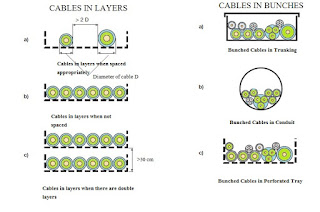
Cables in layers and bunches


Below we will discuss effect of other cables on current carrying capacity of single cable. For same there is factor K2 comes into picture according to installation of  cables laid close together in layers or bunches.

The value of correction factor K2= 1 when:
Distance between two single core cables of different circuits is more than twice that of external diameter of the cable with larger cross section.
Adjacent cables are loaded less than 30% of current carrying capacity.

The correction factors for cables which are either bunched or laid in layers is usually calculated by assuming that  all cables laid in bunches are similar cables and also load on cables is same. The calculation of the reduction factors for bunched cables with different crosssections depends on the number of cables and on their cross sections. These factors have not been tabled, but must be calculated for each bunch or layer.
The reduction factor for a group containing different cross sections of insulated conductors or cables in conduits, or cable ducting is:
where:


K2= 1/(n)1/2

• K2 is the group reduction factor;
• n is the number of circuits of the bunch.

The reduction factor obtained by this equation reduces the danger of overloading of cables with a smaller cross section, but may lead to under utilization of cables with a larger cross section.  Such under utilization can be avoided if large and small cables are not mixed in the same group.
The following tables show the reduction factor (k2).

Reduction Factor for grouped cables:-
Item
Arrangement (Cables Touching)
1
2
3
4
5
6
7
8
9
12
16
20
To be used with current- carrying capacities Reference
1
Bunched in air/ on a Surface/ enclosed
1.00
0.80
0.70
0.65
0.60
0.57
0.54
0.52
0.50
0.45
0.41
0.38
Method A to F
2
Single layer on wall, floor or flat tray
1.00
0.85
0.79
0.75
0.73
0.72
0.72
0.71
0.70
No further  reduction factor for more than  nine circuits or multicore cables
Method C
3
Single layer fixed directly under a wooden ceiling
0.95
0.81
0.72
0.68
0.66
0.64
0.63
0.62
0.61
4
Single layer on perforated tray or vertical tray
1.00
0.88
0.82
0.77
0.75
0.73
0.73
0.72
0.72
Method E & F
5
Single layer on ladder support
1.00
0.87
0.82
0.80
0.80
0.79
0.79
0.78
0.78


Saturday, July 15, 2017

Spark plug working and its construction

Spark plug is used in all automobile engines whether it’s two wheeler, three wheeler, four wheeler or even bigger vehicles. Spark plug is an electrical device which is mounted on cylinder head of internal combustion engines, this electrical spark plug generated a spark which is used to ignites the compressed fuel uses in engines


Spark plug consists of an insulated central electrode which in turn connected through an insulated wire to the ignition coil where ignition is required. This insulated wire may also be connected to the magneto circuit on the outside and form a grounded terminal on the base of the plug. A spark gap in cylinders of and Internal combustion engines is usually divided into:-

(i)            Spark-ignition engines:-
These engines required spark plugs to begin combustion,
(ii)           Compression-ignition engines Known as diesel engines:-
           In these engines air is compressed and then diesel fuel injection is done into the heated compressed air mixture where fuel gets auto ignition.

Compression-ignition engines may use glow plugs to improve cold start characteristics.
There are following functions of Spark plugs:-

There are two primary functions of Spark Plugs
(i)            To ignite the air/fuel mixture.
As discussed earlier electrical spark generated through spark plug , this spark jumps the air gap when voltage applied to spark plug is high enough for crossover of air gap. This spark is used to ignite the air/ fuel mixture in combustion chamber.


(ii)          Removal of heat from Combustion chamber:-
There is misconception that spark plugs create heat but spark plugs are used to remove hear instead. Temperature at the end of spark plug i.e. firing end must be kept low to such levels so as to prevent pre-ignition. Also it should  be kept in  mind that temperature must not be so high so as to prevent unwanted firing.
The heat range of the spark plug must be carefully selected  as if heat range is not correct we will face of troubles. Spark plug firing end temperature is between 900-1,450 degrees. If <900 degrees, carbon polluting is possible. If Temperature is >1500 degree than overheating becomes an issue.
Spark plug acts as a heat exchanged i.e. removes non-useful thermal energy from combustion
chamber and transfers that heat into engine cooling system.
Ability of spark plug to remove heat from spark plug tip and is called as heat range.

Operation of Spark plug :

The spark plug is connected to ignition coil or magneto high voltage generation end. Due to this high voltage at one end there will be potential difference between center of electrode and side electrode. Now due to air gap ignition doesn’t happen now when voltage level reaches to high level then air fuel mixture get ionized and at certain level whole air fuel mixture get ionized and this ionized gas becomes good conductor of electricity and this ignites spark across gap.
Voltage required to generated spark is usually of the level of 20KV-100KV.

When air gap get ionized such that current starts flowing across gap then , temperature level attained will be around 60000 K. This extreme heat causes the expansion of air and fuel mixture to expand more quickly and there will be small explosion.

There are two type of spark plus:-
(i)            Cold Spark plugs
(ii)           Hot spark plugs
Cold Spark Plugs:-
 In these spark plugs heat flow path is short. It is shortened so that there will be faster heat transfer and also you can find small insulator nose on these spark plugs and surface area of this insulator nose is smaller. Due to smaller surface area high heat absorption could not occur in these spark plugs.

Hot Spark Plugs:-
These spark plugs have longer insulator nose so longer heat transfer path. As there is longer heat transfer path so which leads to slower heat transfer to the surroundings cylinder heads.

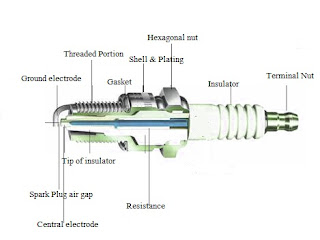
There are following parts of spark plugs:-
(i)            Insulator
(ii)           Hexagonal
(iii)          Shell & Plating
(iv)         Gasket
(v)          Threads
(vi)         Ground electrode
(vii)        Central electrode
(viii)       Spark plug electrode gap
(ix)         Insulator nose or end tip of insulator
(x)     Terminal nut
(xi)     Resistance

Spark plug parts; functioning of different parts of spark plug


(i)    Insulator: Insulator body is usually made from Aluminum oxide ceramic. Then high pressure dry molding technique is used for construction of insulator. When molding is done then it is fired in kiln to temperature that even exceeds the melting point of steel, by doing this insulator will properties such as high dielectric strength, excellent resistance to shock and very high thermal conductivity. On outer surface of spark plug circles so as to provide grip of spark plug.


(ii)  Hexagonal:-This is provided as to provide grip of fixing the spark plug at required place and tightening of spark plug is done from that point only.

(iii) Shell and Plating:- Shell is just below hexagonal and is made using special cold extrusion process. Now this shell is plated to provide protection against the rust and corrosion.


(iv) Gasket:- These may or may not be used in spark plugs. Where gasket is used in Spark plugs there gasket is having folded steel design that provides a smooth surface for sealing purposes. Spark plugs without gaskets have a tapered seat shell which seals through close tolerance.

(v)  Threads:- Threads are used to mount the spark plug at specified location and these threads are made though rolling process instead of cutting the same.


(vi) Ground electrode: Ground electrodes are made from nickel alloy steel and made into different shapes. Property of ground electrode is that under extreme temperature and pressure conditions ground electrode be resistant to both spark erosion and chemical erosion.

(vii)  Center electrode:- Central electrode also should have same properties as that of ground electrode i.e. it must sustain extreme temperature and pressure conditions.


(viii)  Electrode gap:-The gap between ground electrode and center electrode is known as spark plug electrode gap. Gap should be kept as minimum as possible but could not touch the tip of insulator as required spark will not produce in that case.

(ix)  Insulator nose or end tip of Insulator:-There are carbon deposits with passage of time on insulator tip due to sparks generated during period of operation so spark plug nose shape and size is such that it should be capable of removing carbon content, oil and fuel deposits.

(x)  Terminal Nut:- There are two options available in spark plug for connections i.e. spark plug comes with terminal nut or without terminal nut i.e. with threaded nut and connection type or even both. Terminal nut can be detached from spark plug.


(xi) Resistance:- Resistance is provided to high voltage provided to spark plugs so that current could not be very high. Resistance is also kept in thousands. Resistance vary from 1000- 7000 ohms. 5000 ohm is usually cut of point for because it provides a value between where spark plugs are manufactured and where problems seem to appear with high resistance. Most reports Tempest receives about rough running engines associated with high spark plug resistance involve values of 7000 ohms or more. 

Sunday, July 9, 2017

Turbocharger working principle; Turbocharger

Turbocharger is the word most widely used in automobile sector. Now days its is integral part of cars.
Now days turbochargers are used mainly on diesel engines, but now-days initiatives has been taken to use turbo charging of production petrol engines. Turbochargers are most helpful while using them at high altitudes as air is less dense at high altitudes and by using turbocharger we will enable to get more power.  


There are following advantages of turbochargers :-
1.   By using turbocharger engines will go faster.
2.   Engine performance can be improved
Turbocharger consists of pair of fans that connect waste exhaust power from the back of an engine to force more air into the facade, providing more "energy".
Earlier days there is lot of exhaust fumes coming out of vehicles which causes air pollution. This air pollution leads to lot of waste of energy. This waste energy consists of heat as well kinetic energy which get wasted in atmosphere. By using Turbocharger you can use this waste heat and generate more economy and more kinetic energy.
Car engines works on principle that it consists of cylinders where air enters in every cylinder which get mixed with fuel and fuel burns in presence if air which leads to pushing of pistons, shafts turning and gears which leads to spinning of car wheels. Now when piston comes back to its position then it brings waste air and fuel mixes with waste air and which goes out of vehicle as exhaust. Thus we see that fuel goes out along with exhaust as un-burnt. Power generated by engine is directly proportional to how fast fuel get burnt. So if there are more cylinders then more power will get generated as more fuel get burnt every time. Which will leads to faster movement of vehicle.

So there will two options to generate more power:-
1.   By increasing more cylinders
2.   By using turbocharger.
Out of these two method using turbocharger is cheaper and simpler technology. In sports cars there are 8-12 cylinders instead of 4 cylinders in family cars.
How does a turbocharger work?
Turbocharger works in similar principle to that of jet engines. In turbochargers exhaust gas is used to drive a turbine which spins an air compressor and air compressor drives extra air into the car cylinders, Which will ultimately leads to burning of more fuel each second. Which will results into more power.
Turbocharger consists of two fans also called as impellers or gas pumps which are two in number. These are fitted on same shaft so that these will spin together.
One Fan is called turbine and another is called as compressor.
Turbine is usually mounted on exhaust flow from cylinder when exhaust gases flows out of cylinders than this turbine blades starts rotating and so connected shaft also start rotating.
Compressor also mounted on same shaft that of turbine also starts rotating. It is mounted on intake of vehicle which results into giving more air to cylinders.
Now when air is compressed by compressor than air get heated up and heated air will be lesser dense and which leads to lesser help in fuel burning. Thus it would be effective if air coming from the compressor will be cooled before entering the cylinders so to do this heat exchanger is used to remove heat from air.

Advantages of using Turbocharger:-
(i)           These can used both for gasoline as well as diesel engines
(ii)          With turbocharger we will get more power output with same size of engine.
(iii)        Turbocharger will leads to better fuel economy as this will leads to savings of 8-10% of fuel.
(i)           Turbocharger will leads to burning of fuel in more oxygen which leads to clean and complete burning of fuel which leads to reduced air pollution.
(ii)          Reduced size of engine with same capacity of engine will leads to lesser fuel consumption.
Disadvantages of Turbochargers:-
(i)           But there is disadvantage with Turbocharger is that these will leads to worse performance of engines in small engines.
(ii)          Turbochargers leads to complexity of engine.Which will leads to increase maintenance cost.
(iii)         Turbocharging principle is getting the power output from same engine. So there will be more temperature developed in engines and high pressure on pistons. Which leads to failure of engine more frequent, which means life span of engine get reduced.

(iv)              It will require more skills to drive cars fitted with turbocharger, as turbochargers are powered through exhaust gases so this will leads to delay between accelerator and the turbo starts.