Posts

Showing posts from October, 2013

Faults in Electrical Lighting system and Most Severe Fault in lights

We often observe day to electrical faults in our appliances such as  1.Tube rod get faulty  2. Lights not working  these are all happens due to Aging of equipment's Below are the faults which are not in control:- 1. High voltage from source 2. Low voltage from source these types of abnormalities usually effect electronic equipment's such as TV, fridge, Microwave etc.  So to avoid faults in these equipment's usually Stabilizers are installed for them. So that any abnormality in source voltage could not effect our load end.  But severe fault occurred when neutral get breaker from transformer in that case in that case Neutral becomes a floating neutral and phase starts coming in Neutral. Which causes burning of every equipment and even may cause fire if lights not switched off in line.  Now Question arises How voltage starts coming in Neutral? Answer for the same is that During neutral break if Transformer load is balanced then ...
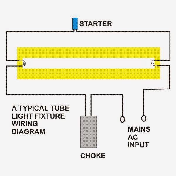
Working principle of Choke; Specifications of Choke

Image
Choke is very important of Tube light. Usually tube light doesn't work without choke. Working:  Normal operating voltage of tube light is about 110 but naturally available voltage is 240 V in India hence the choke comes into picture which gives 110 V output. But for initiating the light (to ionize the gas in the tube) the system, system requires 800 - 1000 V to provide this starter has been used, which block the current flowing from the choke to light hence the voltage will build up across the load. once the maximum voltage reached which starter can withstand, the starter closes the circuit and the build up voltage applied across tube light. Principle:- Choke is actually an Inductor As we know inductor opposes the rate of change of current here we are making current I which is intially drawn to zero with the help of bimetallic contacts present in starter According to formulae E=L*di/dt here L is constant and di is equal to I-0 and dt is time taken for I to bec...

Light Color Temperature; Applications of Different color Tempratures

This is the color of the light as perceived by the human eye. It is measured in degrees Kelvin (°K) • The general terms used for artificial light colors are: Warm White -- 3000 K Cool White   -- 4100 K Daylight       -- 6500 K – This is what our bulbs & tubes are Detailed application of Different color temperature:- 5000- 8000 K -- Daylight White for Petrol Pumps & Winter good shops 4000-5000 K  -- Cool White for Offices, Hospital, industries 3500-4000 K  -- Super Stores, Showrooms 2700-3000 K -- Warm White For Residential Lights, Restaurants 2000-2500 K -- Extra Warm for Display, Street lights

Multimeter, Earthing, Megger, Motors fundamentals

Image
🔌 Fundamentals of Electrical Engineering – Key Industrial Practices 1. Checking Electricity Supply Always use a digital multimeter to verify supply voltage in an industry. A line tester (test pen) may fail over time, and it starts glowing even at 5 V leakage , which may mislead. A multimeter ensures accurate and safe readings. 2. Insulation & Winding Resistance Testing For motor winding resistance and insulation testing , use a Megger (insulation resistance tester). A standard multimeter may not provide correct insulation values due to low test voltage . Megger applies 500V–1000V DC to check insulation strength accurately. 3. Importance of Earthing Grid In industries, multiple earth pits should be interconnected in a grid . Since resistance in parallel decreases, the overall grid resistance is lower. During an earth fault , fault current safely flows to ground through the grid. 4. Separate Grids for Electrical & Electronics Cr...

Fault current direction, Star- Delta starter faults checking, Return path of electrical circuit

Image
Fundamentals of Electrical Engineering – Key Rules to Remember 1. Direction of Electricity Flow Electricity always flows from source to load . It never flows “backward” from load to source. 2. Condition for Current Flow A potential difference (voltage) must exist for current to flow. Current always flows from high potential to low potential . 3. Single-Phase Current Return Path In a single-phase system , whatever current the load draws will return through the Neutral . Neutral ensures circuit completion. 4. Nature of Capacitor Bank Current Current drawn by capacitor banks is reactive current (kVAR) . It is not active (real) power , so do not confuse reactive compensation with actual energy supply. 5. Behavior of Fault Current Fault current always flows backwards from the fault point toward the source . Example: If a motor develops a fault, its overload (O/L) relay trips first , not the transformer. Reason: During fault, the load’s res...

Methods of Earthing and procedure of Earthing pit

Image
Methods of Earthing:  Below are the various method of earthing:- 1.Plate Earthing 2.Pipe Earthing 3.Rod Earthing Plate Earthing:- In this type of earthing plate either of copper or of G.I. is buried into the ground at a depth of 3 Meter or greater than 3 Meters, Earthing plate should not be buried lesser than 3 Meters. Earthing plate is filled with layers of salt and coke not less than 1.5 feet so to provide provide lesser resistance.The earth is securely bolted to an earth plate with the help of bolt nut and washer made of copper, in case of copper plate earthing and of G.I. in case of G.I. plate earthing. For GI earthing Plate Size should be -- 600 mm X 600 mm X 8.30 mm For Copper earthing Plate Size should be-- 600 mm X 600 mm X 3.15 mm Pit Size made for maintenance should be 1 Feet X 1feet so as to provide ease of accessibility of maintenance of these earthing pits and for testing of earthing pits. Below is pictorial view for how to constru...

Why Electrical earthing required and Why Electronic Earthing required ?

Image
Earthing is required for protection of both man and machine. In day to day activities we are using electrical and electronic appliances e.g. for Fans, Television, Lights etc. For protection of both man and machine earthing is used. Earthing provides protection against fault in the system. These faults are associated with very heavy currents which may leads to shock to persons working on the system and even causes failure of equipments. There is underlying principle in electrical systems that "Current always follows low resistance path. H uman body is having high resistance but whenever there is fault in system then that current starts flowing th so if earthing is provided then current will flow in to earth and protect human beings from Shock. Picture shows below how earthing can protect a Human being from Shock. Earthing means connecting the neutral point of supply system or Non current part such as body to the earth via low resistance path. ...

Electricity bill Saving by using Capacitor banks

Image
Capacitor banks are an integral part of every industry as it is required for compensating reactive component of inductive load. Capacitor banks are required to save electricity bill as in inductive load power factor is lagging and more lagging is the power factor more will be your electricity bill. In simple terms if you check your electricity bill and it shows power factor of 0.8 than you will be paying 20% more electricity bill which is huge amount considering the load required by your organization. So there is requirement of capacitor banks which will make power factor more closer to 1. You can't be able to make to 1 but more closer you will be to 1 more savings will in your electricity bill. You can make closer to around 0.98-0.99 power factor.  if you don't know about power factor you must approach an engineer for the same. They will guide exact about the capacitor bank requirement for your organization.  Further investments are not huge for capacitor banks. You h...

Why Three phase Capacitor banks connected in Delta?

Image
Why Capacitor Banks Are Connected in Delta Instead of Star Capacitor banks are widely used in power systems for power factor (PF) improvement and reactive power compensation . Interestingly, you’ll notice that almost all capacitor banks are connected in Delta rather than Star . This choice is not arbitrary—Delta connection provides distinct advantages in terms of efficiency, reliability, and maintenance. Let’s explore them one by one. 1. Lower Maintenance Cost In a Delta-connected capacitor bank , if one capacitor unit (cell) out of three fails, the bank continues to operate in open-Delta mode . The reactive power (kVAR) output only reduces by around 27% , instead of a complete shutdown. Maintenance becomes simpler: the faulty unit can be isolated and replaced without disturbing the other two. This translates to lower replacement cost and improved uptime compared to a star-connected bank. 2. Higher Efficiency In Delta configuration, line current is higher c...

MCCB, Moulded case circuit breaker Working Principle

MCCB name is derived from Moulded case Circuit breaker Breaker. MCCB is used for following purposes :- (i) ON/off of electrical load connected across MCCB (ii) Protection of  an electrical circuit from damage caused by overload ,short circuit and earth fault. Difference between MCCB and Isolator:- This means MCCB also provides protection against overload, Short circuit and earth fault which an Isolator can't do. Isolators are only used to isolate the power supply to circuit. It is used to interrupt the circuit as soon as any fault occurred and they are used in every industry where connected load is having current rating above 100A . Difference between MCCB and Fuses:- MCCB are completely different from fuses. Fuses are used only for interruption  of the circuit and get blown off after it's operation. Although they serve the same purpose in case of any fault in system as these isolate the circuit after getting blown off. But in MCCB , MCCB get tripped in event of f...