Posts

Showing posts from September, 2014

Induction Motors Torque Equation; Torque equation

Image
Torque Equation of Induction Motor: Explained with Factors Affecting Speed-Torque Characteristics Induction motors are widely used in industries due to their robustness, low cost, and simple construction. One of the most important aspects of analyzing an induction motor is its torque equation , which helps in understanding how the motor develops torque under different operating conditions. Torque Equation of an Induction Motor The general torque equation of an induction motor is: T = 3 ω s ⋅ V 2 ⋅ R 2 ′ s ( R 1 + R 2 ′ s ) 2 + ( X 1 + X 2 ′ ) 2 T = \frac{3}{\omega_s} \cdot \frac{V^2 \cdot \frac{R_2'}{s}}{(R_1 + \frac{R_2'}{s})^2 + (X_1 + X_2')^2} Where: T = Torque developed V = Applied stator voltage per phase R1 = Stator resistance R2’ = Rotor resistance (referred to stator side) X1 = Stator reactance X2’ = Rotor reactance (referred to stator side) s = Slip ωs = Synchronous angular speed Key Relation: Torque is Proportional to ...
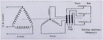
Slip Ring induction motors starting; Slip ring induction motor starter

Image
Starting Of Slip Ring Induction Motors Slip ring Induction motors had external resistance connected in line. These motors are usually started with full line voltage applied across its terminals. During starting of slip ring induction motors the value of starting current is adjusted or kept minimum, by increasing the resistance of the rotor circuit.  The external resistance is connected in star and kept at maximum during starting so to minimize starting current. By increasing the rotor resistance it will not only reduces the rotor current but the stator current too. This means that whenever a resistance is added in rotor circuit that will leads to reduced starting current. Thus because of this, the starting torque is increased due to the improvement in power factor. Usually resistance is added during starting and slowly made out of circuit when motor attains the speed and this resistance is disconnected by using a contactor in line.  Slip ring can be taken in...

DOL, Star-Delta, VFD, Soft- Starters, Auto Transformer Starters advantages and disadvantges

Image
Comparison of Motor Starters: Advantages and Disadvantages Motor starters are essential in controlling the starting current, voltage, and torque of induction motors. Each type of starter has its own application area, benefits, and limitations . Below is a detailed comparison of commonly used starters: 1. Direct-On-Line (DOL) Starter Advantages Very simple design and operation . Low maintenance due to minimal components. Low initial cost . Ease of installation with straightforward circuitry. Suitable for small motors (up to ~10 kW) . Disadvantages Very high inrush starting current (6–8 times full load current). Causes voltage dips in weak supply systems. Not suitable for larger motors (>10 kW) . No power saving during operation. Short acceleration period , making it unsuitable for heavy loads. 2. Star-Delta Starter Advantages Reduces starting current to about 1/3 of DOL value . Prov...

Power plants in electrical systems and Power stations working principle

Power Plant Everyone electrical engineer has very much interest in power generation. Now let's study 1st what is power plant??? A power plant is that industry where power get generated. Power generation usually takes place in Megawatts. From there power is power transmission is done and provided at palaces as per requirements. Power plants requires huge land and water that is why power plants are usually located at a far away distance from main city. For this reason, a power generating station has to not only take care of efficient generation but also the fact that the power is transmitted efficiently over the entire distance. And that’s why, the transformer switch yard to regulate transmission voltage also becomes an integral part of the power plant. At the center of it, however, nearly all power generating stations has an A.C. generator or an alternator, which is basically a rotating machine that is equipped to convert energy from the mechanical domain (rotating tu...

Chemical earthing; Maintenance free earthing; Gel earthing

Image
Chemical Earthing: Working, Treatment Methods, and Benefits Introduction Earthing is one of the most critical safety measures in any electrical system. Traditional earthing methods often require regular maintenance and may not provide consistently low resistance in high-resistivity soil conditions. To overcome these limitations, Chemical Earthing has become increasingly popular in industrial, commercial, and residential installations due to its long life, minimal maintenance, and reliable performance . Why Chemical Earthing is needed? In conventional earthing systems, multiple rods or electrodes may still fail to achieve a low resistance path to ground—especially in rocky or high-resistivity soil. This problem can be solved by artificial treatment of earthing pits , where the soil resistivity around the electrode is reduced by mixing it with conductive substances. Traditional Earthing Treatment Materials In conventional practice, substances like the following are a...