Buy Products here

Sunday, December 6, 2015

Current Transformer Technical Specifications

Current Transformers (CTs): Types, Specifications, and Applications

🔹 Introduction

Current Transformers (CTs) are essential components of electrical power systems. Their primary purpose is to step down high current values into standardized, lower values (usually 5A or 1A), making them suitable for measurement, protection, and monitoring equipment. Without CTs, it would be impossible to directly connect sensitive instruments like meters and relays to high-current circuits safely.


🔹 Types of Current Transformer Designs

CTs are manufactured in different designs based on construction and installation:

  1. Window Type CT

    • The primary conductor (busbar or cable) passes through a “window” in the CT core.

    • Compact and widely used in switchgear and panel boards.


  2. Ring Type CT

    • Circular design, often used around conductors.

    • Easy to clamp around existing cables.

    • Typically used in retrofitting and metering applications.


🔹 Applications of Current Transformers

CTs are broadly classified into two categories based on their function:

  1. Measurement CTs

    • Provide accurate current values for instruments such as ammeters, energy meters, and power analyzers.

    • Designed with high accuracy and intended to saturate under fault conditions, protecting instruments from damage.

    • Common accuracy classes: 0.1, 0.2, 0.5, 1.

  2. Protection CTs

    • Supply current to protective relays and circuit breakers.

    • Must remain accurate even during fault currents (very high currents).

    • Accuracy classes: 5P, 10P (P = Protection, number indicates % allowable error).


🔹 Key Specifications of Current Transformers

1. Rated Transformation Ratio

Ratio=Rated Primary CurrentRated Secondary Current\text{Ratio} = \frac{\text{Rated Primary Current}}{\text{Rated Secondary Current}}
  • Primary current: Actual current in the system (1A to 7500A).

  • Secondary current: Standardized at 5A (or 1A on request).


2. Rated Burden

  • Expressed in Volt-Amperes (VA).

  • Represents the maximum load CT can drive at rated accuracy (e.g., 1–100 VA at 0.8 PF).


3. Accuracy Class

  • Defines permissible error in measurement.

  • Measuring CTs: 0.1, 0.2, 0.5, 1, 3, 5.

  • Protection CTs: 5P, 10P.

  • Example: A 0.2 class CT measuring 100 A may show 99.8A to 100.2A.


4. Current Error (Ratio Error)

Error due to transformation inaccuracy:

% Error=(K×Is)−IpIp×100\% \, \text{Error} = \frac{(K \times I_s) - I_p}{I_p} \times 100

Where:

  • KK = Rated transformation ratio

  • IpI_p = Actual primary current

  • IsI_s = Actual secondary current


5. Accuracy Limit Factor (ALF)

  • Ratio of the maximum primary current up to which CT complies with composite error limits.

  • Important for protection CTs to ensure proper relay operation.


6. Phase Displacement

  • Angular difference between primary current vector and secondary current vector.

  • Positive displacement: Secondary leads primary.

  • Expressed in minutes (′).


7. Composite Error

  • Error caused by harmonic content in secondary current.

  • Critical for relays that depend on waveform accuracy.


8. Bore Diameter

  • Minimum diameter: 40 mm.

  • Larger bore in ring-type CTs allows flexible installation.


9. Highest Withstand Voltage

  • Maximum voltage CT can handle without breakdown.

  • Ring type: 4kV at 50 Hz (1 min).

  • Wound type: 3kV at 50 Hz (1 min).


🔹 General Technical Specifications of CTs

Parameter

Typical Value / Range

Standards

IS/IEC 60044-1 (2003), BS 3938:1973

Insulation Class

E (120°C max)

Operating Frequency

50 Hz

Primary Rating

1A – 7500A

Secondary Rating

5A (1A optional)

Burden

1 – 100 VA

Accuracy Classes

0.1, 0.2, 0.5, 1, 3, 5, 5P, 10P

Ambient Temp.

-20°C to +45°C

Storage Temp.

-50°C to +80°C

Thermal Short-Circuit (Ith)

40×In (wound type), 60×In (busbar type)

Dynamic Short-Circuit (Idyn)

2.5×Ith

Instrument Security Factor (FS)

2.5, 5, 10


🔹 Accuracy Limits of Measuring CTs

Classes 0.1 to 1 (High Accuracy – Metering)


  • Very low ratio and phase errors.

  • Suitable for laboratory and billing applications.

Classes 3 and 5 (General Indicating Instruments)


  • Less accuracy but cost-effective.

  • Used in ammeters and general monitoring.


🔹 Applications of CTs in Power Systems

  1. Metering & Monitoring

    • Energy meters, kWh billing meters, and load analyzers.

  2. Protection

    • Overcurrent, differential, and distance protection relays.

  3. Instrumentation

    • Control panels, switchboards, and SCADA systems.

  4. Safety

    • Isolates high-voltage circuits from measuring instruments.


🔹 Conclusion

Current Transformers are indispensable in modern electrical systems. By converting large primary currents into standardized, safe secondary values, they enable accurate measurement, billing, and reliable protection. The selection of CTs should always consider primary current rating, burden, accuracy class, and application type (measurement or protection).

With proper CT selection and specification compliance, power systems achieve efficiency, safety, and long-term reliability.


⚡ Pro Tip for Engineers:
Always choose a measurement CT with low accuracy class (0.2, 0.5) for metering and a protection CT (5P, 10P) for relay circuits.


Saturday, December 5, 2015

Fleming Left Hand and Right Hand rules

There are two laws in electrical field for determining direction of three parameters Magnetic field, Current, & force.

If you know any of these two remaining parameter direction will be determined by Fleming rules. There are two Fleming rules:-
1.     Fleming Left Hand rule
This rule is applicable for Electric Motors

2.     Fleming Right Hand rule.
This rule is applicable for Electrical generators.

1.     Fleming Left Hand rule:-
According to this law Whenever any current carrying conductor is placed in magnetic field then force is experienced on the conductor in a direction perpendicular to magnetic field and current.
Same is shown by Fleming left hand rule.

Now let’s take an example as shown below where a conductor having length “L” is placed in magnetic field having strength “H”. This magnetic field produces a current “I”. This magnitude of force which acts on conductor is as F= BIL

Fleming Left Hand rule

Now according to Fleming left hand rule, take  three fingers forefinger, Second finger and Thumb all in right angle to each other. Now point fore-finger towards the direction of magnetic field, Second finger will points towards the direction of current then thumb will give the direction of force on conductor. Magnitude of the force on conductor will be = BIL

Where, B represents strength of Magnetic field.

Fleming Left Hand rule


2.     Fleming Right Hand rule:-
According to Faraday's law of electromagnetic induction, whenever a conductor moves inside a magnetic field, there will be an induced current in it.

Now if a conductor forcefully moved inside the magnetic field, there will be a relation between the direction of applied force, magnetic field and the current. Then relation between Magnetic field force, Current and applied force will be given by Fleming right Hand rule.


Now according to Fleming right Hand rule Hold the first finger, Second finger and Thumb of your right hand all in right angle to each other. Then point forefinger towards line of force, then thumb will point towards direction of applied force and Second finger will give direction of current induced in conductor.

Fleming Right Hand rule


Tuesday, December 1, 2015

Battery Calculation for UPS


It is important to select battery size according to UPS capacity otherwise appropriate backup of UPS can’t be obtained.

To calculate battery size according to UPS capacity is as below:-

UPS Backup [in hours]X UPS Capacity in VA = Battery Ah
            Volts* Power factor

From Above formula we see that:-
UPS Backup(in Hrs) means backup requirement of application

UPS Capacity is in VA
Volts is the voltage of battery is usually 12V
Power factor is the power factor of connected load. If you don’t know power factor then take Power factor as 0.8.
Let’s take an example of 500 VA UPS, Battery voltage is 12 V and Power factor as 0.8 and UPS backup required is of 2 hrs then battery size in Ah is as below:-
2X 500 = Battery Ah
12X0.8

Battery Ah= 1000/9.6
It comes approximately as 100Ah so battery requirement is 100 Ah for 500 VA capacity for backup of 2 hrs.

If there are UPS of higher ratings then there will be requirement of more batteries to be either connected in series or parallel.

Then following formula is used in this case:-

UPS Backup [hrs] =N(series) X VoltsX Battery Ah X N(parallel)/(UPS capacity in VA)

Where, Series and parallel of batteries combination is calculated as per user requirement.

If there are two or more batteries are required then following formula is used:-


Backup [in hours] = No. of batteries X Battery Ah X Volts / (Load/p.f.)

Geysers construction; Geysers working principle; Selection of Geysers

Complete Guide to Geysers: Types, Working, Parts, and Safety Features

Geysers are an integral part of every modern household, providing hot water for bathing, cleaning, and cooking. They work on the simple principle of converting electrical energy into heat energy using a heating element. While immersion rods also use the same principle, geysers are far more advanced as they come with storage, control systems, and built-in safety features.


In this article, we will cover:

  • Working principle of geysers

  • Types of geysers

  • Internal parts of geysers

  • Key points to consider before buying a geyser


🔹 Working Principle of a Geyser

A geyser uses a heating element that converts electrical energy into heat. The element is submerged in water inside a tank (in case of storage geysers) or wrapped around a pipe (in instant geysers). As electricity flows through the element, it heats up, and this heat is transferred to the water.

The thermostat and other control systems ensure the water does not overheat, protecting both the geyser and the user.


🔹 Types of Geysers

1. Pressure Type Geysers (Storage Geysers)

  • Have a storage tank where water is kept under pressure.

  • Hot water flows to taps and showers with a good flow rate.

  • Cold water inlet is at the bottom, while the hot water outlet is at the top.

  • This ensures the geyser never runs empty, preventing the heating element from burning out.

✅ Best for: Families needing a steady supply of hot water for multiple uses.


2. Non-Pressure Type Geysers

  • Similar to pressure-type, but come with a single outlet.

  • Hot water is displaced when the cold water valve is opened.

  • A thermostat is installed in the water supply line.

✅ Best for: Small households with basic hot water needs.


3. Instantaneous (Tankless) Geysers

  • Available in both pressure and non-pressure designs.

  • Water is heated on-demand as it flows through a pipe surrounded by a high-rating heating element.

  • Made with durable material for safety and longevity.

✅ Best for: Quick hot water needs, kitchens, and areas with space constraints.


🔹 Internal Parts of a Geyser

A geyser consists of several parts that ensure efficiency, durability, and safety:


  1. Inlet Tube – Allows cold water to enter the geyser.

  2. Heating Element – Converts electricity into heat.

  3. Outlet Valve – Discharges hot water from the tank.

  4. Steel/Fiber Tank – Stores water in storage geysers and houses internal components.

  5. Pressure Relief Valve – Prevents damage from excess pressure.

  6. Thermostat (Cut-off Switch) – Cuts off power when water temperature exceeds safety limits.

  7. Anti-Corrosion Anode Rod – Usually made of magnesium; protects the tank from corrosion.

  8. Insulation Layer – Glass or epoxy lining to retain heat and reduce energy loss.


🔹 Key Factors to Consider Before Buying a Geyser

  1. Star Rating

    • Higher star ratings indicate better energy efficiency.

  2. Standing Losses per Day

    • The energy lost when a geyser remains switched on continuously.

    • Example: A 25-liter, 5-star geyser typically loses only 0.5 kWh/day.

  3. Safety Features

    • Pressure relief valve & thermostat for over-temperature and over-pressure protection.

    • Modern geysers also include short-circuit protection: during a fault, 240V is converted into 12V or 24V, ensuring no electric shock.


✅ Conclusion

A geyser is no longer just a water heater—it’s a safety-tested, energy-efficient appliance designed for modern households. Whether you choose a storage geyser for family use, a non-pressure geyser for limited needs, or an instant geyser for quick heating, understanding the parts, working principle, and safety features will help you make the right buying decision.


⚡ Pro Tip: Always check the BEE star rating, warranty on the heating element, and safety certifications before buying a geyser.


Saturday, November 7, 2015

Circuit diagram of ceiling fan; Fault finding in ceiling fan


Ceiling fan is integral part of every house and Industry. In this article we discuss about wiring of ceiling fans and circuit diagram of ceiling fans.

Ceiling fan are having “Capacitor Start capacitor Run motor”. These motors have capacitor in series with starting winding. Capacitor used for this is electrolytic type. Due to this capacitor single phase get divided into two phases, due to this magnetic field is produced and due to which motor starts to rotate.
Circuit diagram for ceiling fan is as shown below where capacitor is connected in series with starting winding.
Ceiling fan Circuit diagram


How to reverse the direction of ceiling fan?
Direction of Ceiling fan motor can be reversed connecting capacitor with running winding instead of starting winding. 
Wiring of ceiling fan:-
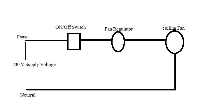
Ceiling fan connected to power supply through a switch and regulator.  Usually phase is rotated through switch and regulator and neutral is directly connected at ceiling fan. Fan regulator is used to control the speed of fan.
Ceiling Fan wiring
Faults in Ceiling Fan:-
There are two types of faults:-
(A)               Mechanical faults
(B)               Electrical Faults
A)     Mechanical faults:-
There are following Mechanical faults occur in fans:-
(i)                  Bent in shaft
(ii)                Bearing problem
Due to all above faults fan may not run properly or run very slowly.
B) Electrical Faults:-
(i) Main running winding get Open circuit/Short circuit.
(ii) Main starting winding get Open circuit/Short circuit.
(iii)               Capacitor get Open circuit/Short circuit.
(iv)              Earth Fault.
(v)                Fan motor rotate in reverse direction.
For (i) & (ii) faults types detection will be done through this method:-
Open/ Short circuit in winding can be detected by using Test bulb arrangement. Arrangement for the same is as shown below:-


Ceiling Fan Fault finding

If  bulb doesn’t glows then there  will  disconnection in the winding.
If bulb glows full then there will be short circuit in the winding.
If bulb glows very dim then there is no fault in the Winding.


For (iii) fault capacitor can be checked by using multimeter for it’s value if value is found low then capacitor will be changed. Usually capacitors used in Ceiling fans have 2.5 microfarad rating.
For (iv) fault earth fault can be checked by using multi-meter.
For (v) fault i.e. for reverse direction same can be changed by changing capacitor bank connection to other winding.

In Single Phase motors why There are more turns on running winding in comparison to start winding?:-
In Running winding no. of turns are kept higher than starting winding the reason behind this is to create phase difference in current in both windings to obtain required torque for rotation of motor.
In Start winding when we keep lower no. of turns than there will be less inductance and more resistance so current will be in phase with voltage. Now by keeping higher no. of turns in running winding we will obtain more inductance and lower resistance which will leads to current lagging behind voltage so we will obtain required phase difference.


Thursday, November 5, 2015

Faraday's law of electromagnetic Induction

Faraday’s Law of Electromagnetic Induction – Principle, Formula & Applications

Michael Faraday (1831) discovered the fundamental principle that governs the working of almost all modern electrical machines — the laws of electromagnetic induction. These laws explain how an EMF (electromotive force) is generated in a conductor whenever there is a change in magnetic flux linked with it.


This principle forms the working basis of:

  • Induction Motors

  • Generators

  • Transformers

  • Inductors


Faraday’s Laws of Electromagnetic Induction

1. Faraday’s First Law

Whenever there is a change in magnetic flux linked with a coil, an EMF is induced in the coil. If the circuit is closed, this induced EMF causes a current to flow.

Ways to change the magnetic field in a coil:

  1. Moving the magnet towards or away from the coil.

  2. Moving the coil into or out of the magnetic field.

  3. Changing the area of the coil placed in the magnetic field.

  4. Rotating the coil relative to the magnet.


2. Faraday’s Second Law

The magnitude of induced EMF is directly proportional to the rate of change of magnetic flux linkages of the coil.

E=NdΦdtE = N \frac{d\Phi}{dt}

Where:

  • EE = induced EMF (Volts)

  • NN = number of turns in the coil

  • Φ\Phi = magnetic flux (Weber)

Flux linkage = N×ΦN \times \Phi


Demonstration of Faraday’s Law

Consider a coil connected to a galvanometer. When a magnet is brought near the coil:

  • The galvanometer needle deflects, showing an induced current.

  • If the magnet is moved in the opposite direction, the needle deflects in the opposite direction, indicating a change in polarity.

  • Faster motion of the magnet produces a larger deflection, showing that induced EMF depends on the rate of change of flux.


Derivation of Induced EMF

If flux linked with a coil changes from Φa\Phi_a at time tat_a to Φb\Phi_b at time tbt_b:

ΔΦ=Φb−Φa\Delta \Phi = \Phi_b - \Phi_a

Change in flux linkages:

Δ(NΦ)=N(Φb−Φa)\Delta (N\Phi) = N(\Phi_b - \Phi_a)

Rate of change of flux linkage:

E=NdΦdtE = N \frac{d\Phi}{dt}

Also,

Φ=B×A\Phi = B \times A

Where,

  • BB = magnetic field strength (Tesla)

  • AA = area of the coil (m²)


Methods to Increase Induced EMF

From the formula, EMF can be increased by:

  1. Increasing magnetic field strength (B): Stronger magnetic field → higher flux → higher EMF.

  2. Increasing number of turns (N): More turns = proportionally higher EMF.

  3. Increasing coil area (A): Larger area links more flux, raising EMF.

  4. Increasing relative speed: Faster movement of coil/magnet cuts flux lines at a higher rate.


Applications of Faraday’s Law

Faraday’s law is the foundation of most electrical machines and devices, including:

  • Transformers – energy transfer between circuits.

  • Induction Motors – convert electrical energy into mechanical energy.

  • Generators – convert mechanical energy into electrical energy.

  • Induction Coils – produce high voltage from low voltage supply.


✅ Conclusion: Faraday’s Law of Electromagnetic Induction is the backbone of electrical engineering. Without it, the modern world of power generation, transmission, and electric machines would not exist.


Sunday, November 1, 2015

Cable size and current carrying capacity

Cable size and current carrying capacity for XLPE insulated cable, non-armored, Twin or multicore cable is as below:-


Conductor operating temperature is 90 degree Celsius
Ambient temperature: 30 degree Celsius.

XLPE non armored cable


Cable size and current carrying capacity for XLPE insulated, Armored, Twin or multicore cable is as below:-
Conductor operating temperature is 90 degree Celsius
Ambient temperature: 30 degree Celsius. For air and 20 degree Celsius for ground for installations require to comply with BS: 7671

Cable size and current carrying capacity for XLPE armored cable


Correction factors:-
For Ambient temperature:
Ambient temperature in degree Celsius
Correction Factor
25
1.02
30
1.00
35
0.96
40
0.91
45
0.87
50
0.82
55
0.76
60
0.65
65
0.58
70
0.50
75
0.41
80


Ground Temperature
Ambient temperature in degree Celsius
Correction Factor
10
1.07
15
1.04
20
1.00
25
0.96
30
0.93
35
0.89
40
0.85
45
0.80
50
0.76
55
0.71
60
0.65
65
0.60
70
0.53
75
0.46
80
0.38

Soil Resistivity
Thermal resistivity Km/W
Rating factor for cables buried in Ducts
Rating factor for direct buried cables
0.5
1.28
1.88
0.8
1.20
1.62
1.0
1.18
1.50
1.5
1.10
1.28
2.0
1.05
1.12
2.5
1.00
1.00
3.0
0.96
0.90


Underground Cables vs Overhead Cables

  1. Basic Difference Parameter Overhead Cable/Line Underground Cable Installation ...