Buy Products here

Friday, July 28, 2017

Designing a plant; Reduction factors while laying cables in bunches and layers

There are following procedure to be adopted for correct dimensioning of a plant

(i)            Load Analysis:-
First step in dimensioning of a plant is to check for connected load and their location

Now check for location of power distribution panels
Now we can calculate cable requirement i.e. length of cables and path of cable laying
Now we will do calculations of total power consumption while taking account utilization factors and demand factors


(ii)          Transformer and generator size calculations:-
Transformer and generator size are usually selected 15-30% more in comparison to total connected load considering future prospectus.

(iii)         Conductor size selection-
Now we calculate cable size according to load requirement of various connected loads. Cable selected may be copper or aluminum. Cables selection must also consider voltage drop at load current under specific reference conditions.

(iv)         Selection of Protective circuit breaker:-
Short circuit calculations can be done and accordingly switchgear busbar and switchgear should be selected. It is always considered to select circuit breaker with breaking capacity higher than short circuit current. Rating of circuit breaker should be higher than rated current of load connected to circuit breaker. Characteristics of circuit breaker should be according to connected to load.

(v)          Protection of conductors:-
For protection against overload circuit breaker rating should be higher than the load current but should be lower than Rated current carrying capacity of conductor.
In case of short circuit protection circuit breaker setting should be lower than short circuit current withstand by conductor.

(vi)         Protection of Load:-
For protection of load such as motors which constitute 70% of total load of any industrial and commercial establishment overload relays and other protections must be provided after breaker so that tripping of relays leads to protection of load. For protection of human beings from electrical shocks it is always recommended to install RCCB or ELCB.


Selection of the cable
For installation and calculation of current carrying capacity of cables in Industrial, commercial and houses cable selection should be as per International standard IEC 60364-5-52 i.e. “Electrical installations of buildings Part 5-52 for “Selection and Erection of Electrical Equipment- Wiring systems”.

There are following ways and parameters are used to select the cable type:
a)    Conductivity of Material:-
The foremost parameters to be considered while selection of cables is conductivity of material. Copper is costlier then aluminum but selection depends upon cost of material, size of material , weight of material, resistivity of material and resistivity to corrosive environment. Generally copper is having higher current carrying capacity i.e. 30% higher than aluminum conductors for same cross-sectional area, this is due to fact that aluminum is having higher resistivity than copper i.e. 60% higher than copper conductor.

b)     Insulating Material used for conductors:-
There are so many insulating materials used for copper or aluminum conductors. Insulating material may or may not be used for conductors. Materials used for conductors may be PVC, XLPE. Insulating material will affects maximum temperature that a cable able to carry under normal and short circuit conditions.

c)     Type of conductor:-
            There are following types of conductors:-
a)    Bare conductor
b)    Single core cable without sheath
c)    Single core cable with sheath
d)    Multicore cable with sheath and armored
e)    Flexible multicore cable
Cable can be selected according to mechanical resistance, degree of insulation and difficulty of installation required by the method of installation.

Conductors reduction factor while laying the cables in different arrangement of laying the cables:-
It has been observed that with presence of other cables laid around the cable , cable current carrying capacity is influenced significantly. This happens because heat dissipation of single cable get affected due to presence of other cables nearby.
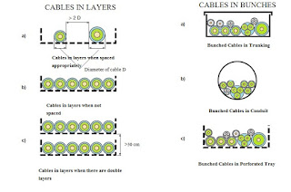
Cables in layers and bunches


Below we will discuss effect of other cables on current carrying capacity of single cable. For same there is factor K2 comes into picture according to installation of  cables laid close together in layers or bunches.

The value of correction factor K2= 1 when:
Distance between two single core cables of different circuits is more than twice that of external diameter of the cable with larger cross section.
Adjacent cables are loaded less than 30% of current carrying capacity.

The correction factors for cables which are either bunched or laid in layers is usually calculated by assuming that  all cables laid in bunches are similar cables and also load on cables is same. The calculation of the reduction factors for bunched cables with different crosssections depends on the number of cables and on their cross sections. These factors have not been tabled, but must be calculated for each bunch or layer.
The reduction factor for a group containing different cross sections of insulated conductors or cables in conduits, or cable ducting is:
where:


K2= 1/(n)1/2

• K2 is the group reduction factor;
• n is the number of circuits of the bunch.

The reduction factor obtained by this equation reduces the danger of overloading of cables with a smaller cross section, but may lead to under utilization of cables with a larger cross section.  Such under utilization can be avoided if large and small cables are not mixed in the same group.
The following tables show the reduction factor (k2).

Reduction Factor for grouped cables:-
Item
Arrangement (Cables Touching)
1
2
3
4
5
6
7
8
9
12
16
20
To be used with current- carrying capacities Reference
1
Bunched in air/ on a Surface/ enclosed
1.00
0.80
0.70
0.65
0.60
0.57
0.54
0.52
0.50
0.45
0.41
0.38
Method A to F
2
Single layer on wall, floor or flat tray
1.00
0.85
0.79
0.75
0.73
0.72
0.72
0.71
0.70
No further  reduction factor for more than  nine circuits or multicore cables
Method C
3
Single layer fixed directly under a wooden ceiling
0.95
0.81
0.72
0.68
0.66
0.64
0.63
0.62
0.61
4
Single layer on perforated tray or vertical tray
1.00
0.88
0.82
0.77
0.75
0.73
0.73
0.72
0.72
Method E & F
5
Single layer on ladder support
1.00
0.87
0.82
0.80
0.80
0.79
0.79
0.78
0.78


Saturday, July 15, 2017

Spark plug working and its construction

Spark Plug in Automobiles – Working, Functions, Types, and Parts Explained

A spark plug is one of the most critical components of internal combustion (IC) engines. Whether it’s a two-wheeler, three-wheeler, four-wheeler, or even larger automobile engines, spark plugs are indispensable in gasoline-powered vehicles.

They are mounted on the cylinder head and generate an electric spark to ignite the compressed air-fuel mixture, enabling combustion and engine power generation. While diesel engines rely on compression ignition, they may use glow plugs for cold starts, whereas petrol engines cannot function without spark plugs.


🔧 Functions of a Spark Plug

A spark plug performs two primary functions:

1. Ignition of Air-Fuel Mixture

  • The ignition coil or magneto provides 20 kV – 100 kV high voltage.

  • This creates a potential difference between the central and ground electrodes.

  • Once the voltage exceeds the dielectric strength of the gap, the air-fuel mixture gets ionized.

  • The ionized gas becomes a conductor, allowing a spark to jump across the gap.

  • The spark temperature can reach ~60,000 K, igniting the mixture and producing a small explosion for power.

2. Heat Dissipation from Combustion Chamber

  • Contrary to the misconception, spark plugs do not create heat; instead, they act as a heat exchanger.

  • They transfer unwanted heat from the firing end to the engine’s cooling system.

  • The firing end temperature must remain between 900°C – 1,450°C:

    • Below 900°C → risk of carbon fouling.

    • Above 1,500°C → risk of overheating and pre-ignition.

  • The ability of a spark plug to remove heat is termed its heat range.


⚡ Types of Spark Plugs

1. Cold Spark Plug

  • Short heat path → faster heat transfer.

  • Smaller insulator nose → less surface area for heat absorption.

  • Best suited for high-performance engines that run at high speeds and loads.

2. Hot Spark Plug

  • Longer insulator nose → slower heat dissipation.

  • Maintains higher tip temperatures → helps prevent carbon fouling.

  • Ideal for low-speed, city-driving engines.


🛠️ Parts of a Spark Plug and Their Functions

A modern spark plug consists of 11 major parts:

  1. Insulator – Made of aluminum oxide ceramic, ensures dielectric strength and thermal conductivity.

  2. Hexagonal Section – Provides grip for tightening/removal using a wrench.

  3. Shell & Plating – Made from extruded steel, plated for corrosion resistance.

  4. Gasket (optional) – Ensures proper sealing; some plugs use a tapered seat instead.

  5. Threads – Machined by rolling, allow plug to be screwed into the cylinder head.

  6. Ground Electrode – Nickel alloy, resists spark erosion and high-temperature corrosion.

  7. Central Electrode – Similar alloy, conducts high-voltage current.

  8. Electrode Gap – Distance between central and ground electrodes where the spark jumps.

  9. Insulator Nose (Tip) – Designed to resist carbon, oil, and fuel deposit buildup.

  10. Terminal Nut – Connection point for ignition coil wire; may be threaded or detachable.

  11. Resistance – Built-in resistance (1kΩ – 7kΩ) limits excessive current. Most common is 5kΩ for stability.


🔍 Spark Plug Operation (Step-by-Step)

  1. Ignition coil generates 20,000–100,000 volts.

  2. Voltage reaches the spark plug’s central electrode.

  3. Once the dielectric strength of air gap is exceeded, the mixture ionizes.

  4. Spark forms across the electrode gap.

  5. The spark’s extreme temperature ignites the compressed air-fuel mixture.

  6. Controlled explosion produces power, while spark plug dissipates heat into the cooling system.


✅ Key Takeaways

  • Spark plugs are essential for spark-ignition engines, while diesel engines use glow plugs only for starting.

  • Their two main roles are:

    1. Igniting the air-fuel mixture.

    2. Dissipating combustion heat.

  • Proper heat range selection is critical to avoid fouling or overheating.

  • Cold plugs suit high-speed engines, hot plugs suit low-speed city use.

  • Spark plugs consist of 11 precision-engineered parts, each ensuring reliability under extreme temperature and pressure.


⚠️ Disclaimer: This article is for educational and informational purposes only. Always refer to the manufacturer’s guidelines for spark plug selection, installation, and maintenance in vehicles.


Sunday, July 9, 2017

Turbocharger working principle; Turbocharger

Turbocharger is the word most widely used in automobile sector. Now days its is integral part of cars.
Now days turbochargers are used mainly on diesel engines, but now-days initiatives has been taken to use turbo charging of production petrol engines. Turbochargers are most helpful while using them at high altitudes as air is less dense at high altitudes and by using turbocharger we will enable to get more power.  


There are following advantages of turbochargers :-
1.   By using turbocharger engines will go faster.
2.   Engine performance can be improved
Turbocharger consists of pair of fans that connect waste exhaust power from the back of an engine to force more air into the facade, providing more "energy".
Earlier days there is lot of exhaust fumes coming out of vehicles which causes air pollution. This air pollution leads to lot of waste of energy. This waste energy consists of heat as well kinetic energy which get wasted in atmosphere. By using Turbocharger you can use this waste heat and generate more economy and more kinetic energy.
Car engines works on principle that it consists of cylinders where air enters in every cylinder which get mixed with fuel and fuel burns in presence if air which leads to pushing of pistons, shafts turning and gears which leads to spinning of car wheels. Now when piston comes back to its position then it brings waste air and fuel mixes with waste air and which goes out of vehicle as exhaust. Thus we see that fuel goes out along with exhaust as un-burnt. Power generated by engine is directly proportional to how fast fuel get burnt. So if there are more cylinders then more power will get generated as more fuel get burnt every time. Which will leads to faster movement of vehicle.

So there will two options to generate more power:-
1.   By increasing more cylinders
2.   By using turbocharger.
Out of these two method using turbocharger is cheaper and simpler technology. In sports cars there are 8-12 cylinders instead of 4 cylinders in family cars.
How does a turbocharger work?
Turbocharger works in similar principle to that of jet engines. In turbochargers exhaust gas is used to drive a turbine which spins an air compressor and air compressor drives extra air into the car cylinders, Which will ultimately leads to burning of more fuel each second. Which will results into more power.
Turbocharger consists of two fans also called as impellers or gas pumps which are two in number. These are fitted on same shaft so that these will spin together.
One Fan is called turbine and another is called as compressor.
Turbine is usually mounted on exhaust flow from cylinder when exhaust gases flows out of cylinders than this turbine blades starts rotating and so connected shaft also start rotating.
Compressor also mounted on same shaft that of turbine also starts rotating. It is mounted on intake of vehicle which results into giving more air to cylinders.
Now when air is compressed by compressor than air get heated up and heated air will be lesser dense and which leads to lesser help in fuel burning. Thus it would be effective if air coming from the compressor will be cooled before entering the cylinders so to do this heat exchanger is used to remove heat from air.

Advantages of using Turbocharger:-
(i)           These can used both for gasoline as well as diesel engines
(ii)          With turbocharger we will get more power output with same size of engine.
(iii)        Turbocharger will leads to better fuel economy as this will leads to savings of 8-10% of fuel.
(i)           Turbocharger will leads to burning of fuel in more oxygen which leads to clean and complete burning of fuel which leads to reduced air pollution.
(ii)          Reduced size of engine with same capacity of engine will leads to lesser fuel consumption.
Disadvantages of Turbochargers:-
(i)           But there is disadvantage with Turbocharger is that these will leads to worse performance of engines in small engines.
(ii)          Turbochargers leads to complexity of engine.Which will leads to increase maintenance cost.
(iii)         Turbocharging principle is getting the power output from same engine. So there will be more temperature developed in engines and high pressure on pistons. Which leads to failure of engine more frequent, which means life span of engine get reduced.

(iv)              It will require more skills to drive cars fitted with turbocharger, as turbochargers are powered through exhaust gases so this will leads to delay between accelerator and the turbo starts.

Sunday, July 2, 2017

Nature of electricity; Electricity Nature

The Nature of Electricity: Structure, Charges, and Potential Difference

Electricity is one of the most essential forms of energy in modern life, powering everything from household appliances to industrial machinery. But what exactly is the nature of electricity? At its core, electricity is the result of the movement of electrons. Natural phenomena such as lightning are examples of electricity in action, while most of the electricity we use daily is generated in power plants.


To truly understand the nature of electricity, we must first look at the structure of the atom.


Structure of the Atom

Every substance in the universe is made up of atoms. An atom is the smallest particle of an element that still retains its chemical properties. Atoms consist of three fundamental particles:

  • Electrons (–): Negatively charged, very lightweight particles.

  • Protons (+): Positively charged particles, about 1,840 times heavier than electrons.

  • Neutrons (0): Neutral particles with no charge.

The nucleus of an atom contains protons and neutrons, while electrons orbit around the nucleus, similar to how planets revolve around the sun.

The atomic number of an element indicates how many electrons orbit the nucleus. Electrons closer to the nucleus are tightly held, while those farther away are loosely bound and can be easily displaced.


Role of Electrons in Electricity

Electricity is primarily the movement of electrons. Neutrons do not play a role in electricity.


For example:

  • The hydrogen atom (the simplest atom) has only one proton and one electron. The electron is tightly bound to the proton, making it difficult to remove.

  • In larger atoms with multiple electrons, the outermost electrons (called valence electrons) are weakly held and can move freely.

When external energy is applied (e.g., friction, heat, or a lightning strike), these loosely held electrons can be dislodged. Once free, they move randomly through the material, creating electric current.


Conductors and Insulators

  • Good conductors: Materials like copper and aluminum, where electrons are easily dislodged and flow freely.

  • Poor conductors (insulators): Materials like rubber, glass, and wood, where electrons are tightly bound and resist movement.

This is why copper and aluminum are widely used in power transmission.


How Electric Charge is Produced

Atoms can lose or gain electrons:

  • An atom that loses electrons becomes positively charged.

  • An atom that gains electrons becomes negatively charged.

Thus, an imbalance of charges leads to the development of electric charge.

  • Like charges repel each other (positive–positive or negative–negative).

  • Unlike charges attract each other (positive–negative).

This principle is known as the Law of Electric Charges.


Potential Difference and Flow of Current

The ability of an electric charge to do work is called its potential. When two points have different electric potentials, a potential difference (voltage) is created.

This potential difference causes electrons to flow from the point of higher potential to the point of lower potential, resulting in an electric current.

In simple terms:

  • Voltage (V): The driving force (potential difference).

  • Current (I): The actual flow of electrons.

  • Resistance (R): The opposition to electron flow (varies with material).

This relationship is defined by Ohm’s Law:

V=I×RV = I \times R

Conclusion

The nature of electricity lies in the behavior of electrons within atoms. By understanding atomic structure, electric charge, and potential difference, we can better appreciate how electricity is generated and transmitted. This fundamental knowledge is not only important for scientists and engineers but also helps everyday users understand the invisible force that powers our modern world.


⚡ Disclaimer: This article is for educational purposes only. While every effort has been made to ensure accuracy, electricity is a complex subject. For practical electrical work or safety-related applications, always consult a certified electrical engineer or relevant technical guidelines.


Friday, June 23, 2017

Comparison between lean burn and Rich Burn engines

Comparison between lean burn and Rich Burn engines:-
After certain emission calibration levels Lean‐burn gas engines are more economical  and these can even operate at higher loads,
But in rich‐burn engines have lower emission levels with a single after treatment these are more tolerant of broad fuel ranges and ambient conditions, and generally have better transient load capability.


Principle of operation of Rich Burn engines:-
Rich‐burn engines operate at principle of stoichiometric air/fuel ratio (AFR) according to this principle air in exact quantity is supplied to burn all of the fuel.  This will leads to reduction in nitrogen oxides (NOx), carbon monoxide (CO), hydrocarbons (HC), and HAPS (Hazardous Air Pollutants) after certain treatment for all in one i.e. by using catalytic converter used in cars.

Lean burn engines working principle:-
In these engines Lean‐burn engines use a lot of excess air. These engines take up to twice the amount needed in rich burn engines for complete fuel combustion. Excess air used in lean burn effectively cools down the peak combustion temperatures in the cylinder, this will reduces the NOx production and allows low engine‐out emissions without the need for an after treatment system in many applications.
In these engines there are advantages of reducing the detonation probability thus it will leads to higher Brake Mean Effective Pressure loads and an optimized combustion phasing. This results in higher power density and usually produces better fuel efficiency.

Emissions in Rich-burn engines:-
Rich‐burn engines have emissions of 12‐16 g/bhph‐hr NOx i.e. “5,000 ‐ 6,500 mg/Nm3@ 5 percent 02 in the exhaust gas “, in most stoichiometric/AFR exhaust gas composition and the increased exhaust gas temperatures allow the use of a three‐way catalyst.
These engines  have high NOx conversation rates i.e. above 99 percent that significantly reduce all three major types of engine‐out emissions ‐ NOx, CO and HC , Since there are low emissions that will destroy inferior but hazardous pollutants like formaldehyde (CH20).
Rich-burn engines emission are below 50 mg/Nm3 NOx and ultra‐low total hydrocarbon emissions, which will leads to decreased overall greenhouse gas footprint.


Emissions in Lean Burn Engines:-
If we have requirement of High power density and we required highest possible efficiency at moderate emission levels of 500 or 250 mg/Nm3 NOx (@ 5 percent 02 in the exhaust gas) lean burn engines have advantage. These engines at an adequate gas quality they deliver BMEP levels of up to 24 bar with electrical efficiencies up to 46.5 percent  without the need for a NOx or THC after treatment system.

To lower the NOx emissions that are reached by rich‐burn engines with a three‐way‐catalyst, lean-burn engines require selective catalytic converters with urea injection.
Oxidation catalysts perform most of the CO reduction in lean‐burn engines but  the fuel gas must be very pure. These catalysts also can reduce CH20 emissions ‐ again, if the gas is pure ‐ but their low exhaust temperature limits hydrocarbon conversion efficiency.

Operational flexibility
Rich burn engines can operate effectively only at clean fuels such as Natural gases. These will not operate at Biogas, Sewage gas or landfill gases as these will poison the three way catalyst. High combustion temperatures restrict specific output and the BMEP, so there is lower efficiency than with lean‐burn engines operating at higher air/fuel ratios. If lean burn engines are calibrated to operate at extremely low NOx levels (ultra‐lean), their efficiency begins to degrade so that the difference between rich‐burn and lean‐burn fuel consumption is minimized. Since lean‐burn engines have a much higher AFR ‐ with about 10 percent excess oxygen in the exhaust ‐ their engine‐out NOx emissions are only 5 percent to 10 percent of the amount discharged by a rich‐burn engine. Lean‐burn engines require selective catalytic reduction (SCR) treatment to obtain the lowest possible NOx emissions levels in the exhaust gas. SCR injects a controlled amount of urea into the catalyst to convert NOx to nitrogen. Being able to operate at a more optimal AFR with an SCR system makes the lean‐burn engine very efficient and allows high break mean effective pressures.


Oxidation catalysts are used to provide most of the CO and NMHC reduction in lean‐burn engines but, as with other catalytic systems, the fuel gas has to be very pure. These catalysts also can reduce CH20 emissions ‐ again, if the gas is pure ‐ but their low exhaust temperature limits hydrocarbon conversion efficiency

Saturday, April 22, 2017

Air conditioner Complete selection and installation guide

Why You Must Know Room Area Before Selecting an Air Conditioner

When it comes to buying an air conditioner, one of the most common questions in every customer’s mind is:
👉 “What size of AC is right for my room?”


Most people rely on sellers, friends, or other customers’ experiences. But here’s the truth: an incorrectly sized air conditioner will either waste electricity or fail to cool your room properly.

That’s why understanding the room area and cooling requirements is crucial before you make your purchase.


Why AC Sizing Matters

  • If AC capacity is higher than required:

    • Excessive power consumption

    • Cooling cycle stops early → humidity not removed → damp and clammy feeling

    • Lower efficiency and shorter equipment life

  • If AC capacity is lower than required:

    • Room will never reach comfortable cooling

    • AC runs continuously → higher electricity bills

    • Equipment wears out faster

Thus, the right-sized AC ensures effective cooling, proper dehumidification, and optimal electricity use.


Functions of an Air Conditioner

  1. Cooling – lowers the room temperature to the desired level

  2. Dehumidification – removes excess moisture from the air

If an oversized AC is installed, the room may cool quickly but without sufficient dehumidification, leaving it cool but humid, which feels uncomfortable.


How to Measure Room Area

  • Square or rectangular room: Length × Width

  • Triangular room: (Length × Width) ÷ 2

  • Irregular-shaped room: Divide into smaller sections, calculate area, then sum them up

For accurate measurement, take the help of an AC technician or sales expert.


Cooling Capacity Requirement

Air conditioners are rated in BTUs/hour (British Thermal Units).

  • 1 Ton of cooling ≈ 12,000 BTU/hour

Here’s a simplified Room Size vs AC Size Guide:

Room Area (sq. ft.)

BTU/hr Required

AC Size (Tons)

100 – 150

5,000

0.5 ton

150 – 250

6,000

0.5 ton

250 – 300

7,000

0.75 ton

350 – 400

9,000

1 ton

450 – 550

12,000

1 ton

700 – 1,000

18,000

1.5 ton

1,000 – 1,200

21,000

1.75 – 2 ton

1,200 – 1,400

23,000

2 ton

1,500 – 2,000

30,000

2.5 ton

2,000 – 2,500

34,000

3 ton


Additional Factors Affecting AC Capacity
  1. Room Orientation & Sunlight

    • Shaded rooms → reduce capacity by 10%

    • Sun-facing rooms → increase capacity by 10%

  2. Number of Occupants

    • Standard: 2 people

    • Add 600 BTU/hour per extra person

  3. Kitchen Usage

    • Cooking adds extra heat load

    • Increase capacity by 4,000–5,000 BTU/hour (≈30%)


Indoor & Outdoor Unit Installation

Indoor Unit

  • Install at 7–9 ft height for effective airflow

  • Place where air distributes evenly

  • Ideally above the bed (but not blowing directly on the body)

  • Adjust louvers for better airflow

Outdoor Unit

  • Install in an open space (terrace/external wall) with free airflow

  • Position above indoor unit for better refrigerant flow

  • Keep distance ≤15 meters between indoor & outdoor units

  • Ensure easy accessibility for maintenance


Single-Stage vs Two-Stage Compressor ACs

  • Single-Stage AC:

    • Works only at full capacity

    • Less efficient, higher energy bills

  • Two-Stage AC:

    • Operates at both high and low levels

    • Adjusts cooling as per outside temperature

    • Saves electricity and provides more comfort


Conclusion

Choosing the right size of air conditioner is not just about comfort, but also about energy savings, efficiency, and long-term durability. By measuring your room size, calculating BTU requirements, and considering additional factors (sunlight, occupants, kitchen use), you can select the most suitable AC for your home.


Disclaimer

The above information is for educational purposes only. Actual AC size requirements may vary based on room insulation, ceiling height, climate conditions, and manufacturer specifications. Always consult a qualified HVAC technician before making your final purchase.


Selection of Air Inflator for Vehicle

 The important point before purchasing Air inflator for Vehicle is that you should not select a tyre inflator only by its maximum PSI. You s...