Electric Meter, or Watt-hour Meter, a device that measures the quantity of electric energy. One kilowatt hour is the quantity of electric energy needed to supply 1,000 watts of electricity for a span of one hour.
An electrical power business uses electric meters to quantify the number of electricity consumed by each. It bills the customer for the level of electricity and reads the meter occasionally.
The most frequent kind is basically an electrical induction motor that drives a string of geared wheels linked to gauges on the face of the meter. Such a meter was created with alternating current to be used. It comprises a metal disc which is free to rotate between them and two electromagnets. Current pulled through the building's electrical circuits powers directly by current in the incoming power lines; the other, one electromagnet. The interaction causes the disc to rotate. Two permanent magnets near the border brake of the disc the disc in this type of manner the speed is proportional to the level drawn. As the disc rotates, it turns the chain of geared wheels linked to the gauges on the face of the meter.
Details of single phase meter working is as below:-
Single phase induction type energy meter is, in addition, popularly known as watt-hour meter. This name is given to it. This post is concentrated about its functioning and its constructional features. Induction type energy meter basically includes following components:
1. Driving system
2. Moving system
3. Braking system
4. Registering system
Driving system
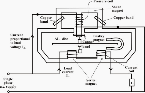
A coil having large number of turns is wound on the middle limb of the shunt magnet.
This voltage coil has many turns and is ordered to be as highly inductive as potential. Quite simply, the voltage coil creates a high ratio of inductance to resistance.
This induces thus the flux and the current, to lag the supply voltage by almost 90 degree.
Building
Single-phase induction kilowatt hour meter - Building
A flexible copper shading bands are provided on the central limb of the shunt magnet to make supply voltage is approximately 90 degree and the phase angle displacement set up by shunt magnet.
The copper shading bands may also be called the power factor compensator or compensating loop. The flux produced by this magnet is proportional to, and in phase with the load current.
Moving system
The moving system basically consists of a light rotating aluminium disc mounted on shaft or a vertical spindle. A gear arrangement connects the rotating shaft that supports the aluminium disk to the clock mechanism on the front to provide advice that used up energy.
The time varying (sinusoidal) fluxes generated by shunt and series magnet induce eddy currents in the aluminium disc.
The interaction between both of these magnetic fields and eddy currents set up a driving torque in the disc.
The quantity of rotations of the disc is therefore proportional to the energy consumed by the load in a particular time interval and is generally measured in kilowatt hours (Kwh).
Braking system
The disk passes between the magnet gaps.
Redirecting a number there form or by shifting the position of the brake magnet, the rate of the rotating disk can be controlled.
Single-stage induction kilowatt hour meter scheme
The counting or registering system basically consists of gear train, driven by pinion or worm gear on the disc rotating shaft, which turns pointers that indicate on dials how many times the disk has turned.
The energy meter thus discovers and adds or integrates all the instantaneous power values to ensure entire energy used over an interval is therefore understood.
Thus, this kind of meter can also be called an "integrating" meter.
Working of Single phase induction sort Energy Meter
The fundamental working of Single phase induction kind Energy Meter is just focused on two mechanisms:
Mechanism of spinning of an aluminum disc which is made to rotate at a speed proportional to the electricity.
Mechanism and showing the level transferred.
Lets have a look over these mechanism in few words:
Mechanism of turning of an aluminum disc
Which is made to rotate to the electricity.
The metallic disk is acted upon by two coils. One coil is joined 0 r ordered in such a fashion it produces a magnetic flux in proportion to the voltage and the other generates a magnetic flux in proportion. 90 degrees delay the field of the voltage coil.
This creates eddy currents in the disk and the effect is such that there is a force applied on the disc in proportion to the product of the instantaneous current and voltage.
A permanent magnet exerts an opposing force proportional to the speed of rotation of the disk - this acts as a brake which causes the disk to stop spinning when electricity stops being drawn rather than allowing it to spin faster and faster. This causes the disk to rotate to the power used.
Mechanism of displaying the amount of energy transferred
According to amount of rotation.
The aluminum disc is supported by a spindle that has a worm gear which drives the cash register. The register is a number of dials which record the level of energy used.
It should be noted that with the dial pointer type, adjacent pointers generally rotate in opposite ways because of the gearing mechanism.
Electronic watt-hour meters are usually higher priced than versions that are electro-mechanical, but are more precise. They are able to supply such characteristics as the capability to record individually the energy used up during different times of day and the capacity to report meter readings by means of signs sent to the power company through the power lines.
An electrical power business uses electric meters to quantify the number of electricity consumed by each. It bills the customer for the level of electricity and reads the meter occasionally.
The most frequent kind is basically an electrical induction motor that drives a string of geared wheels linked to gauges on the face of the meter. Such a meter was created with alternating current to be used. It comprises a metal disc which is free to rotate between them and two electromagnets. Current pulled through the building's electrical circuits powers directly by current in the incoming power lines; the other, one electromagnet. The interaction causes the disc to rotate. Two permanent magnets near the border brake of the disc the disc in this type of manner the speed is proportional to the level drawn. As the disc rotates, it turns the chain of geared wheels linked to the gauges on the face of the meter.
Diagram above shows how single phase energy meter works, similar will be applicable for three phase energy meters.
Details of single phase meter working is as below:-
Single phase induction type energy meter is, in addition, popularly known as watt-hour meter. This name is given to it. This post is concentrated about its functioning and its constructional features. Induction type energy meter basically includes following components:
1. Driving system
2. Moving system
3. Braking system
4. Registering system
Driving system
A coil having large number of turns is wound on the middle limb of the shunt magnet.
This voltage coil has many turns and is ordered to be as highly inductive as potential. Quite simply, the voltage coil creates a high ratio of inductance to resistance.
This induces thus the flux and the current, to lag the supply voltage by almost 90 degree.
Building
Single-phase induction kilowatt hour meter - Building
A flexible copper shading bands are provided on the central limb of the shunt magnet to make supply voltage is approximately 90 degree and the phase angle displacement set up by shunt magnet.
The copper shading bands may also be called the power factor compensator or compensating loop. The flux produced by this magnet is proportional to, and in phase with the load current.
Moving system
The moving system basically consists of a light rotating aluminium disc mounted on shaft or a vertical spindle. A gear arrangement connects the rotating shaft that supports the aluminium disk to the clock mechanism on the front to provide advice that used up energy.
The time varying (sinusoidal) fluxes generated by shunt and series magnet induce eddy currents in the aluminium disc.
The interaction between both of these magnetic fields and eddy currents set up a driving torque in the disc.
The quantity of rotations of the disc is therefore proportional to the energy consumed by the load in a particular time interval and is generally measured in kilowatt hours (Kwh).
Braking system
The disk passes between the magnet gaps.
Redirecting a number there form or by shifting the position of the brake magnet, the rate of the rotating disk can be controlled.
Single-stage induction kilowatt hour meter scheme
The counting or registering system basically consists of gear train, driven by pinion or worm gear on the disc rotating shaft, which turns pointers that indicate on dials how many times the disk has turned.
The energy meter thus discovers and adds or integrates all the instantaneous power values to ensure entire energy used over an interval is therefore understood.
Thus, this kind of meter can also be called an "integrating" meter.
Working of Single phase induction sort Energy Meter
The fundamental working of Single phase induction kind Energy Meter is just focused on two mechanisms:
Mechanism of spinning of an aluminum disc which is made to rotate at a speed proportional to the electricity.
Mechanism and showing the level transferred.
Lets have a look over these mechanism in few words:
Mechanism of turning of an aluminum disc
Which is made to rotate to the electricity.
The metallic disk is acted upon by two coils. One coil is joined 0 r ordered in such a fashion it produces a magnetic flux in proportion to the voltage and the other generates a magnetic flux in proportion. 90 degrees delay the field of the voltage coil.
This creates eddy currents in the disk and the effect is such that there is a force applied on the disc in proportion to the product of the instantaneous current and voltage.
A permanent magnet exerts an opposing force proportional to the speed of rotation of the disk - this acts as a brake which causes the disk to stop spinning when electricity stops being drawn rather than allowing it to spin faster and faster. This causes the disk to rotate to the power used.
Mechanism of displaying the amount of energy transferred
According to amount of rotation.
The aluminum disc is supported by a spindle that has a worm gear which drives the cash register. The register is a number of dials which record the level of energy used.
It should be noted that with the dial pointer type, adjacent pointers generally rotate in opposite ways because of the gearing mechanism.
Electronic watt-hour meters are usually higher priced than versions that are electro-mechanical, but are more precise. They are able to supply such characteristics as the capability to record individually the energy used up during different times of day and the capacity to report meter readings by means of signs sent to the power company through the power lines.
No comments:
Post a Comment
Note: Only a member of this blog may post a comment.