Slip Ring induction motors starting; Slip ring induction motor starter
Starting Of
Slip Ring Induction Motors
Slip ring Induction
motors had external resistance connected in line. These motors are usually
started with full line voltage applied across its terminals. During starting of
slip ring induction motors the value of starting current is adjusted or kept
minimum, by increasing the resistance of the rotor circuit. The external
resistance is connected in star and kept at maximum during starting so to
minimize starting current. By increasing the rotor resistance it will not only
reduces the rotor current but the stator current too.
This means that
whenever a resistance is added in rotor circuit that will leads to reduced
starting current. Thus because of this, the starting torque is increased due to
the improvement in power factor.
Usually resistance
is added during starting and slowly made out of circuit when motor attains the
speed and this resistance is disconnected by using a contactor in line. Slip ring can be taken in line by using manually
also. The 3-phase supply to the stator has a switching contactor along with
over-load and no or low-voltage protective devices. There might be also an
interlock provided to ensure the proper sequential operation of the control
gear and starting devices.
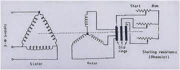

Slip ring motors circuit diagram is as shown above.
Torque curve of Slip ring motors is shown above
As per torque
formula
Torque is directly
proportional to resistance.
So as the
resistance is high in slip ring motors torque is also high during starting.
As these motors
have considerably high starting torque with low starting current, these motors
can be started on load. The external resistance is used only for the starting
purpose, after which the motor gradually picks up the speed, the resistance
gradually cut-off. These rings are isolated after the motor reaches its rated
speed. The carbon brushes are lifted and the rings are short circuited thus
making them very similar to squirrel cage motors.
Applications of Slip Ring Induction Motors
These motors are
used where the load is intermittent and comes on very sharply for brief
periods, such as a punching machine. A heavy flywheel is fitted in the drive,
preferably between the work and any speed-reduction gears. The flywheel shares
the load with the motor, thus enabling a motor of lower rating to be employed.
For load sharing to take place automatically, the motor speed should drop
considerably as the load increases and this is ensured by using a motor having
a high full-load slip, say for example 10%.
Characteristics Of Slip Ring Induction
Motor
As other induction
motors consists of Stator and Rotor circuits slip ring motors also have same
Stator circuit there is only difference in rotor circuit. Rotor circuit consists
of external resistance in the circuit. The stator circuit is slip ring motors
is rated as same in the squirrel cage motor, but the rotor is rated in frame
voltage or short circuit current. The frame voltage is the open circuit voltage
when the rotor is not rotating and gives the measure of turns ratio between the
stator and rotor. The short circuit current is the current flowing when the
motor is operating at full speed, with the slip rings shorted and the full load
applied to the motor shaft.
Advantages of Slip-Ring Motors:
1. These are used
where there are high Inertia loads as these
motors have excellent starting torque.
2. These motors
have low starting current then other induction motors.
3. It is easy to control the speed of the motor from
50% to 100% of the full speed,
Disadvantages of Slip Ring Motors
1. Higher brush and
slip ring maintenance required,
2. As the brush
wears out, it may lead to intermittent contact, and thus heavy sparking.
3. Also speed
control of motor comes along with increased losses as heat comes across
resistance.


Comments
Post a Comment