Search This Blog

Saturday, August 15, 2015

Copper rotors advantages over Aluminum rotors; Premium energy efficient motors

Copper has high electrical conductivity then aluminum so this feature it ideally suitable for rotor bars and end rings in induction motors. Usually aluminum was used for manufacturing of rotor bars as they have low melting temperature. But now techniques has been developed to develop rotors with die cast copper. Copper has melting temperature then aluminum so it difficult to manufacture.

Due to high conductivity and lower resistive losses so rotors with copper make the motor more energy efficient than aluminum.

Copper rotors


There are following advantages of using copper die cast rotors instead of aluminum rotors:-

11.     Copper rotors will leads to reduced size of motor for same efficient motors using aluminum rotors. For same efficient motors as that of copper rotor length of aluminum rotor needed to be increased to about 15-20% . Increase in rotor length increase the cost of many of the other components used in manufacturing the motor.

As we know that stator and rotor in motors contain stampings and stacks of lamination steel. Now when we Increase the length of the rotor it will leads to increase in the amount of electrical grade lamination steel that is required, and the number of stampings.
In stators there is winding of copper. Now when there is increase in length of aluminum rotor the length of the stator increase which directly impacts the copper wire content and processing time requirements.


This will leads to heavier motor. Which means bearings of higher load bearing capacity needed to be installed. Thus we see that copper rotors initial cost is offset by other changes in motors.

22.    Copper rotors will leads to motor power savings and  enhanced efficiency motors
 Motors account for more than 70% of the electrical energy use in industrial sector worldwide. Motors with copper rotors will leads to Incremental improvements to electric motor efficiency means more power savings.

33.   Copper rotors also provide better global environmental benefits as copper rotors consume less power which will leads to lower carbon emissions.  With growing environmental consciousness of businesses, governments, and consumers; and high global energy costs and carbon taxes drive the need to continuously seek more energy efficient materials and processes.


Although there is higher cost of manufacturing the copper rotors but payback period for using in industrial motors is less than 1 years. Copper rotors enables to achieve up to 2.5% efficiency gains in current aluminum based products without increasing the size of the motor. 

Sunday, August 9, 2015

Lubrication Interval and Vibration Level in motors

Lubrication Interval of Motor

In Induction motors Lubrication plays an important part for efficient operation of motor.
Timely lubrication also leads to lower breakdown of motors.

Below is the lubrication interval of the motor.


Lubrication Interval of Motor
Vibration Level In motors:-

Vibration of an electrical machine is closely related to its assembly on the application and, thus, it is generally desirable to perform vibration measurements under installation and operational conditions. Nevertheless, to allow evaluation of the vibration generated by the electrical machine itself in a way to allow reproducibility of the tests and the obtaining of comparative measurements, it is necessary to perform such measurements with the machine uncoupled, under controlled test conditions. The test conditions and vibration limits described here are those found in IEC 60034-14.
The severity of vibration is the maximum value of vibration found among all the recommended measurement points and directions. The table below indicates the recommended admissible values of vibration severity under IEC standard 60034-14 for the frames IEC 56 to 400, for degrees of vibration A and B.


Sunday, August 2, 2015

Dimmer for lights; Dimmer electronic; Dimmer working principle

Dimmers are used for controlling brightness of the light. Dimmers are used to change the waveform of the voltage applied to the light. Dimmers are used for controlling voltage of resistive loads lights i.e. for CFL’s, Bulbs, resistive incandescent, LED lights etc.


Dimmer chops the voltage applied to light. Which will allows chopped part of voltage to pass to light.  Dimmers are available in different sizes and ratings, they have sizes as small as size light switch to control domestic lighting and have as higher rating for controlling lighting installations in theatres and architectural lightings.


Dimmer for lights
Above pic shows small size of dimmer used domestic lights

Dimmer is wired in series with the lamp. The lighting dimmer control is done by potentiometer. To control voltage in lighting potentiometer needed to be rotated to control the voltage.

Wiring of dimmer in circuit

From above pic you can see how Dimmer is wired in circuit.

Dimmers are available in different ratings from 600-1000 W rating, depending upon the rating of light. Remote controlled dimmer switches are also available. X10 models are available for house lighting and Modern professional dimmers DMX and DALI models are generally digitally controlled.


Also Modern dimmers are semiconductor controlled instead of old resistive controlled as semiconductor dimmers have more efficiency. In old resistive controlled dimmers voltage is dissipated across resistance but as semiconductor controlled dimmers is solid state dimmers i.e. they can switch between low resistance as ÖN State and high resistance as ÖFF state so they have low power dissipation and leads to higher efficiency and saving of power. Due to these semiconductor dimmers they smaller sizes of dimmers are available in the market. These semiconductor dimmers can have easily remote control operation available. These switches generate heat and radio-frequency interference that can be avoided by placing inductor as part of circuitry. 


Semiconductor dimmer

Semiconductor based Dimmer internal circuit is shown above

Dimmer Types:-

Dimmer have following types:-
1.       Rheostat Dimmers
2.       Saltwater type—Liquid Dimmers
3.       Coil Rotation Transformer
4.       Auto-Transformer Dimmer
5.       Solid State Dimmer

Dimmers have three types of curves:-
1.       Linear
2.       Square
3.       S

Analog dimmers O/P wasn’t directly proportional to Input, An analogue dimmer dim slowly at first, quickly in middle and slowly at top.

Usually televisions uses Square Law curve. Which allows finer control of light at top, this is done to allow accurate trimming of color temperature of lighting. Theatrical dimmers use softer “S” or linear curves.

Digital dimmers can be designed for any shape of curve for operation. 

Dimmers Preheat function:-
Dimmers also provide preheat function. Whenever there is switching of high intensity incandescent lamps this will reduce the life of lights due to high inrush current. These high current usually occurs due to switching from cold to hot state. This can be avoided by setting dimmer between 5% to 10% as light will appears to be off at that level but it will provide preheating of light i.e. it will leads light not getting cool down. This will leads to higher life of light.


Sunday, July 19, 2015

Voltage drop reduction methods; Voltage drop an evil in electrical systems

Voltage drop is always a problem for electrical engineers. Every possibility is explored by electrical engineers to minimize voltage drop to minimum level so to do effective utilization of generated voltage and losses due to voltage drop.
We Know that Voltage= Current X Resistance
Now Resistance= Resistivity X length of conductor/ Area of conductor
Now we get Voltage= Current X Resistivity X Length of conductor
                                                       Area of conductor


Now we see that voltage has relation with length  of conductor , current carried by conductor, Area of conductor.
So by following means Voltage drop across a conductor can be minimized :-
1.       Increasing the area of conductor
2.       Decreasing length of conductor
3.       Decreasing current across conductor
In additional to above there is fourth factor by which voltage drop can be reduced i.e. by decreasing conductor temperature. Now that factor comes from resistivity as resistivity decreases with decrease in temperature. So there are four factors by which voltage drop across a conductor can be minimized.

1.      Increase the Area of conductor or by increasing Number of Conductors:-
By using parallel conductors or by increasing area of conductor resistance per unit length will be decreased, which ultimately leads to decrease in voltage drop across conductor. With reduced voltage drop across conductor will leads to increased efficiency across conductor. By using parallel conductors will leads to lower the overall power losses which are otherwise more in conductors of standard size


2.     Decrease Current across conductors:-
By limiting current across conductor voltage drop across conductor get reduced proportionally. This can be achieved by reducing the load connected to conductor. Usually capacitor bank is connected across the system so to compensate reactive load current. This way current across conductor get reduced which will leads to lower voltage drop across conductor.
But one should keep in mind that capacitor should not be connected in oversize, otherwise it will leads to higher current across conductor due to over compensation. Which will leads to higher voltage drop.

3.     Decreasing Conductor Length
By reducing length of conductor during design stage voltage drop can be minimized. It should be always practice to keep load near to panels so that voltage drop can be minimized.

4.     Decreasing Temperature of conductor

When conductor is heavily loaded then that will leads to heating up the conductor, thus we can say that conductor temperature is dependent on the factors listed above. As we know that conductor temperature is a major factor in conductor resistance, and therefore in voltage drop. The temperature coefficient of copper i.e., α, is 0.00323/°C, which means resistance change of about 0.3% for each °C of temperature change.
Temperature coefficient of resistance equation is as below:-
R2 = R1 [1 + α · (T2 – T1)]
Where R1 is the resistance (Ω) at temperature T1 and R2 is the resistance at temperature T2.

Temperature T1 is often referenced at 75°C. As noted, voltage drop is a particular concern at high conductor loadings, where conductor temperatures will also be high.

Voltage drop for length of conductor


Table above shows the Maximum Recommended Lengths of Single-Phase Branch Circuits, as a Function of Load Current, Supply Voltage, and Conductor Size, for Both 3% and 1.5% Voltage Drops.


We can say that Voltage drop is necessary evil in electrical systems and great burden for electrical engineers. 

Saturday, July 11, 2015

Transformer Oil Testing; IS:335 for Transformer oil; Transformer BDV values

Transformer are integral part of Electrical Systems. In same way Transformer oil is Integral part of Transformers. Although Dry type transformers are available in market , but still oil type transformers are most widely used and  preferred worldwide.

FUNCTIONS OF TRANSFORMER OIL
1.  Transformer oil provide dielectric strength to transformer insulation system.
2. It also provide efficient cooling to Transformer as heat generated in winding get dissipated through transformer oil.

PRODUCTION OF TRANSFORMER OIL                            
¬  Transformer oil is hydrocarbon product mainly  oil contains
(i)                  Naphthenic
(ii)                Paraffinic and
(iii)               Aromatics.

Following procedure is adopted for obtaining the TOBS (Transformer Oil Base stock) from crude oil which is buried from earth crust :-
(i)      Distillation
(ii) Acid treatment
(iii) Neutralization
(iv) Water wash
(v) Hot air blowing.
(vi) Clay treatment process on Transformer Oil Base Stock (TOBS) will give us the finished transformer oil.
(iii)    Finally after hot filtration operation transformer oil is ready for filling the transformers.

DETERIORATION ASPECTS OF TRANSFORMER OIL
There are so many reasons for deterioration of Transformer oil few of them are as listed below:-

(i)      Deterioration due to water .
(ii)    Deterioration due to the chemical decomposition.
(iii)   Deterioration due to the oxidation.
(iv)  Deterioration due to the contamination by gases.
(v)    Deterioration due to  the electrical stresses.
(vi)  Deterioration due to the thermal stresses.
(vii) Deterioration due to the effect of oxidation products.
(viii)Deterioration due to the physical contamination.


PRECAUTIONS INVOLVED IN  TRANSFORMER OIL SAMPLING.
¬  The utmost care should be taken to avoid contamination of samples with external impurities such as dust and moisture.
¬  Attention is drawn to the danger of sampling in rainy or foggy weather.
¬  The hands of the sampler should not come into contact with the samples.
¬  Care should be taken when sampling oil colder than the surrounding air, to avoid contamination by condensation.
TRANSFORMER OIL
Specifications for Testing of transformer oil.
¬  IS-335
¬  ASTM-D3487
¬  IEC-60296
¬  BS-148
¬  JIS-2320
IS-335 SPECIFICATION
APPEARANCE: 
Clear transparent and free from suspended matter and or sediments.
 DENSITY:
IS-1448 P(16)

HYDROMETER/THERMOMETER  
DESIGN VALUE—0.89 gms/ml @29.5°C max

 KINEMATIC VISCOCITY:
IS-1448 P(25)
CONSTANT TEMPERATURE BATH THERMOMETERS/STOP WATCH


DESIGN VALUE—27cSt @ 27 °C max 
¬  INTERFACIAL TENSION:IS-6104
INTERFACIAL TENSIO METER
DESIGN VALUE—0.04N/M max
¬  FLASH POINT:IS-1448 P(21)  
PENSKY MARTINS CLOSED CUP FLASH POINT TESTER/THERMOMETERS.
DESIGN VALUE—140 °C min
¬  POUR POINT:IS-1448 P(10)
CLOUD POINT&POUR POINT APPARATUS/THERMOMETERS        
DESIGN VALUE--   -6 °C max
¬  NEUTRALIZATION VALUE:IS-1448 P(2)
CONICALFLASKS/BURETTES/MEASURING CYLINDERS/BURETTE STANDS/ VOLUMETRIC FLASKS                        DESIGN VALUES—
A. TOTAL ACIDITY : 0.03mgKOH/gm           B.  INORGANIC ACIDITY: NIL
¬  ELECTRIC STRENGTH(BDV): IS-6792


 BDV TEST SET
 DESIGN VALUES
  A. UN FILTERD :30kv min                                  B. FILTERD : 60kv min
¬  DIELECTRIC DISSIPATION FACTOR (TAN DELTA):IS-6262 
TANDELTA TEST SET/OIL CELL HEATER/OIL CELL.
DESIGN VALUE : 0.002 max
¬  RESISTIVITY : IS-6013
RESISTIVITY TEST SET/OIL CELL HEATER /OIL CELL
DESIGN VALUES
A. 1500*10E12 Ohm-cm @27 °C min         
              B.  35*10E12 Ohm-cm @90 °C min
¬  PRESENCE OF ANTI OXIDATIVE INHIBITOR :IS13631                     
              MEASURING CYLINDERS/PIPPETES/ BURETTES/BURETTE STANDS
              DESIGN VALUE : NOT DETCTABLE
¬  WATER CONTENT : IS-13567                
              AUTO MATIC KARLE FISHER TITRATOR/WEIGHING BALANCE
              DESIGN VALUE : 50PPM max
¬  CORROSIVE SULPHUR : IS-335 ANNEX-B
 TEMPERATURE CONTROLLED OVEN/CONOCAL FLASKS/FORECEPS
 DESIGN VALUE : NON CORROSIVE
¬  OXIDATION STABILITY : IS-335 ANNEX-C 
OXIDATION STABILITY BLOCK/VACUUM PUMP/OXIDATION TUBES/G-4 FILTERS / BURETTES / BURETTE STANDS / CONICAL FLASKS/WEIGHING BALANCE.  
DESIGN VALUES
 A.NEUTRALIZATION VALUE:0.4mgKOH/gm
               B. SLUDGE % BY MASS :0.1max
¬  AGEING CHARACTERISTICS: IS-12177   
             AGEING OVEN /WEIGHING BALANCE/ VACCUME PUMP/ G-4 FILTERS/ BURETTES/BURETTE  STANDS /  CONICAL FLASKS.                              
    DESIGN VALUES           
A. RESISTIVITY@27DegC-2.5Ohm-cm min 
 B. RESISTIVITY@90DegC-0.2Ohm-cm min
C. TANDELTA@90DegC-0.2 max                    
D.TOTAL ACIDITY -0.05mgKOH/gm            
E. TOTAL SLUDGE –0.05%


NABL RECUREMENTS IN OIL LAB
¬  Equipment history cards
¬  Measurement uncertainty calculations.
¬  Regular calibrations of instruments from NABL accredited laboratories.
¬  Interlab comparison
Replicate testing
APPEARANCE TEST
¬  APPEARANCE
¬  Measurement uncertainty calculation for transformer oil appearance test
¬  Sources of uncertainty
a) Improper sampling
         b) Presence of sediments and suspended matter in the bottles used for sampling
         c)  Persons skills
       a) Improper sampling :
 To avoid the uncertainty due to improper sampling the following care should be taken
   1) Don’t use the cotton waste while sampling
   2) Don’t pickup the sampling in dust and foggy weather
   3) Clean the sampling point (pipe end) before sampling
b) Presence of sediments and suspended matter in the bottles used for sampling :
The test results may be effect due to the contamination of sediments and suspended matter, if any present in the sampling bottles. Bottles should be thoroughly clean before sampling by using the following cleaning agents as per the sequence
1) Tap water
2) Soap solution 
3) Tap water
 4) Hot distilled water
 5) Acetone and allow for oven drying at 110°C for 1hr. And then vacuum with the vacuum pump.    
Breakdown VOLTAGE TEST
Measurement uncertainty calculation for BDV test on transformer oil 
Sources of uncertainty
 1) Test results obtained              
2) BDV test set resolution                                                           
3) BDV test set calibration                                                           
4) Atmospheric condition
Results obtained .
Repeated measurements on sample  transformer oil sample                                                                                  a)  ( 68,74,72,60,68,64)   = 67.6kv
             b) (66,72,80,64,68,62)    = 68.6kv
             c) (68,70,70,68,80,76)    = 72.0kv
             d) (72,62,76,68,82,68)   = 71.3kv                                
              e) (64,66,78,72,68,70)   = 69.6kv
          Average value  = 69.82kv
St. Deviation= Ö(-2.22)2+(-1.22)2+(2.18)2+(1.48)2+(-0.22)2/4
                       = Ö(4.9284+1.4884+4.7524+2.1904+0.0484)/4
                      = 1.8308
Type A uncertainty = 0.818kv
2) BDV test set resolution :
      (B1)uncertainty due to BDV test set resolution= 2 / 2 Ö3 = 0.577kv
3) BDV test set calibration :                                                                         
(B2)uncertainty due to BDV test set calibration =1.9 / 2  =.95kv                                                                    
   Type B uncertainty = Ö(B1)2+(B2)2                                                                                               
                                               = Ö(0.572)2+(0.95)2 = 1.1115kv                                                 
    Combined uncertainty = Ö(Type A)2+(Type B)2  
     Combined uncertainty = Ö(Type A)2+(Type B)2  
                                              = Ö (0.818)2+ 1.1115)2= 1.38kv
Note :4
Room temperature and relative Humidity maintained at 27°C and 44% RH respectively so uncertainty due to Atmospheric Conditions is not Considered
¬  Expended uncertainty = 2 x 1.38 = 2.76kv
¬  At 95% confidence level with respeet to 69.82kv

69.82 ±  2.76  

Friday, July 10, 2015

Protection in Solar Panels;Bypass diode

For protection of Solar panels bypass diodes are used details for protection of solar panel is as described below:-

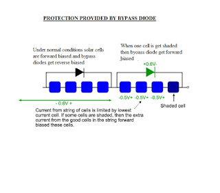
Bypass diode is also known as free-wheeling diode and is connected in parallel to every solar cell or for group of solar cells. It is not advisable to use bypass diode for every solar cell as it is too costly so it is used for group of solar cells. Bypass diode is connected in parallel with opposite polarity to a solar cell. As we know that solar panel is constructed using individual solar cells and solar cells are made from layers of silicon semiconductor materials. One layer of silicon is treated with a substance to create an excess of electrons. This becomes the negative or N-type layer. The other layer is treated to create a deficiency of electrons, and becomes the positive or P-type layer similar to transistors and diodes. During normal operation of solar panels all solar cells are forward biased and bypass diode is reverse biased as bypass diode acts as open circuit. The damaging effects of hot-spot heating may be avoided through the use of a bypass diode. Bypass Diodes prevent the current(s) flowing from good, well-exposed to sunlight solar cells overheating and burning out weaker or partially shaded solar cells by providing a current path around the bad cell.


Bypass diodes are basically used for protection in case of shades/Dark. Normally one bypass diode is used for every 15 solar cells. Therefore for 60 cell module bypass diode required are 4 nos.
The voltage across the unshaded solar cells depends on the degree of shading. For example, if one cell is completely shaded, then the unshaded solar cells will be forward biased by their short circuit current and the voltage will be about 0.6V (this is taken as an example). If the cell is only partially shaded, the some of the current from the good cells can flow through the circuit, and the remainder is used to forward bias each solar cell junction, causing a lower forward bias voltage across each cell. The maximum power dissipation in the shaded cell is approximately equal to the generating capability of all cells in the group. 


Bypass Diode functioning
Above figure is self explanatory showing how bypass diode provides protection from Hot Spot heating. 


Process by Which Hot-Spot heating is prohibited by Reverse bias Diodes
If a solar cell is reverse biased due to a mismatch in short-circuit current between several series connected cells, then the bypass diode conducts, thereby allowing the current from the good solar cells to flow in the external circuit rather than forward biasing each good cell. The maximum reverse bias across the poor cell is reduced to about a single diode drop, thus limiting the current and preventing hot-spot heating.


Friday, July 3, 2015

Mono-Crystalline Vs Poly-Crystalline Solar Panels

Comparison between Mono-crystalline and Multi-crystalline Solar Panels:-
Both types of solar panels use Silicon crystalline panels. Only difference is the purity of silicon used during manufacturing process. More purity of silicon we use better will be the efficiency of solar panels, but more purity we achieve is at the expense of more cost.

Mono-Crystalline Solar panels
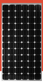
Typical Mono-Crystalline solar panels are typically dark black in colour. Also corners are missing in these types of solar panels. They have uniform look which indicates that they have high purity of silicon. Mono-crystalline solar cells are usually made out of silicon blocks which are cylindrical in shape.

Mono-Crystalline Solar Panels


Poly-crystalline Solar Panels:-
Pole crystalline solar panels are usually light or dark blue colour, some patches are lighter than others. Poly-crystalline solar panels are usually perfect rectangular and these don’t have round edges. Raw silicon is melted and poured into a square mold, which is cooled and cut into perfectly square wafers.


Poly-Crystalline Solar Panels


Mono-Crystalline solar cells have slighter higher efficiency than poly-crystalline solar cells. But Poly-crystalline solar panels are slightly cheaper to manufacture than mono-crystalline panels. Also there is tighter spacing of cells in poly-crystalline solar panels than mono-crystalline panels which will defeat the higher efficiency of mono-crystalline solar panels. Also poly-crystalline solar panels have better performance at higher temperature than mono-crystalline solar panels have better performance at higher temperature than mono-crystalline solar panels.
There is effective utilization of space in Poly-crystalline solar panels than mono-crystalline solar panels as there is wastage of space in mono-crystalline solar panels due to shape of single crystals, So slighter lower efficiency will get offset by better utilization of space, Which will leads to higher efficiency per m2 in case of Poly-crystalline solar panels.
Mono-crystalline Vs Poly-Crystalline Solar Panels
1.     Mono-Crystalline solar panels have the highest efficiency rates as these are made out of the highest-grade silicon. Typical efficiency of these panels is 15-20% as compared to poly-crystalline solar panels which have efficiency range of 13-15%. This is due to lower silicon purity.


  1. Mono-Crystalline solar panels have long life usually these solar panels manufacturer’s will give 25-year warranty.
  2. Mono-Crystalline solar panels have better performance than poly-crystalline panels at low light conditions.
  3. Process of Manufacturing Poly-crystalline solar panels is simpler and less costly than mono-crystalline. Also wastage of silicon during manufacturing is lower in poly-crystalline solar panels.
  4. Poly-crystalline solar panels have better performance than mono-crystalline solar panels.
  5. Mono-crystalline solar panels have thin-films which will tend to be more aesthetically pleasing since they have a more uniform look compared to the stippled blue color of polycrystalline silicon.