Search This Blog

Thursday, August 25, 2016

Fault locating methods for High and low tension cables

In electrical systems its usual that cable may get faulty there are following methods of checking the type of fault in cable:-
1.      Using Meggar for LT Cables:-
Meggar is most commonly used method for checking the fault in cables. If Meggar is used at 500V/ 1000V DC then cable shows infinite value If cable is Ok.  if value lies above 100 Mohm then cable is also acceptable it indicates only that there cable is having some moisture which will be dried out when cable is put on load but if value falls below this value upto 50 Mohm then it will be used where there were light loads.


If there is value is near to zero than cable should not be used as if cable insulation level between two leads is zero this means cable is short circuited. If Cable insulation with respect their leads is ok but between lead and earth is zero than this indicates cable get short circuited with armored.
In Meggar we can check resistance value also in this 2 leads one is placed on resistance and other is placed on common. 500/1000V is applied to two terminals of cable and resistance value is measured.

2.      Using Hi-Pot For testing High tension cables
Hi-Pot test is used for testing High tension cables in this test DC voltage is applied to cable for 5-15 min’s. According to IEEE-400 hi-pot voltage for a 15-kV class cable is 56 kV for an acceptance test and 46 kV for a maintenance test.

There are fault locators which are used to identify the location of fault in a cable as Most of HT cables are laid underground so it becomes very much necessary to find out the location of fault as in this case cable replacement will not be easy and also it will leads to lot of cost of replacement of whole cable.

1.           Divide rule:-
This method is very old one but still used in LT system, in this method cable is cut
down into 2 pieces and check for insulation resistance one piece of cable will give perfect value other will give low values so higher valued cable will be used and other faulty part will be again tested used divide rule.


    2.  High voltage test:-

This is another old method, in this method high voltage is applied to faulty cable this will leads to loud noise which you can hear above ground. In method very high voltages upto the level of 25-32 KV needed to be applied to cable so that noise can be hear able.   This will also leads to heating of cable as high currents generated during that process. Thus it will cause degradation of cables.

     3. Time domain reflectometry 

This is new technology for detection of faults in under ground HT cables. In Time domain reflectometry  there is a device which sends a low-energy signal through the cable if cable is perfect than cable returns that signal in a known time and in a known profile. 

There following limitations of TDR:-
(i)         It does not Provide accurate location of  pinpoint faults. This method is accurate upto 1% of testing range.
(ii)        It cannot see faults-to-ground with resistances much greater than 200 ohms. So, in the case of a "draining fault" rather than a short or near-short, TDR is blind.

     4. High-voltage radar methods:-

There are following types of this method:-

(i)         Arc reflection
(ii)        Surge pulse reflection
(iii)       Voltage pulse reflection.
Lets discuss them one by one :-

(i)      ARC Reflection Method:-
This method consists of  TDR with a filter and thumper (High voltage).  In this method filter is used to limit current and voltage due to surge on cable which means minimal stress to the cable. This method provides an approximate distance to the fault


(ii)     Surge pulse reflection method
This method uses a current coupler and a storage oscilloscope with a thumper. The advantage of this method is its superior ability to ionize difficult and distant faults. Its disadvantages are that its high output surge can damage the cable, and interpreting the trace requires more skill than with the other methods.

(iii)    Voltage pulse reflection method
This method uses a voltage coupler and an analyzer with a dielectric test set or proof tester. This method provides a way to find faults that occur at voltages above the maximum thumper voltage of 25kV.


Sunday, July 17, 2016

Effects of Higher and lower voltage on Induction motors

Motor name plate consists of voltage range for operating motors. Operating the motors both lower and higher than motor name rating will leads to reduced efficiency and may also leads to premature failure of motors.
Effects of low voltage on Induction motors 
When voltage applied to motor get lower than name plate lower range of voltage than for fixed amount of power at lower voltage current drawn by motor get increased. Higher current will leads to exceeding motor name plate current rating that will leads to heating up the motor and even burning out the motor if over-current persists.

Power in motor is = Voltage X Current X Power factor
So lower the voltage higher will be current drawn by motor as power factor is same for motor.
Effects of high voltage on Induction motors:-
 There is often assumption made from Power relation that Since low voltage increases the current drawn by motors, then high voltage must reduce the current draw this lower current will leads to lower heating effect of motor. But results are somewhat different High voltage on a motor tends to push the magnetic portion of the motor into saturation. Usually this happens when motor voltage exceeds certain limit of voltage level of motor. Thus Higher voltage will cause the motor to magnetize the iron beyond the point where magnetizing is practical by drawing higher current.
This higher current drawn by motor will leads to overheating of motor and thus will leads to shortening life of motor.
Usually  motors rated at 220 and 440V with voltage tolerance band of 5-10% . If voltage increases on decreased than this band level then there will be drastic effects on performance and efficiency of motors. Also this will not means that you will continue to operate motors at extreme levels of this voltage level otherwise this will shorten life of motors.
Low voltage can lead to following:-
a.      Overheating
b.      Shortened life

c.       Reduced starting ability and
d.      Reduced pull-up and pullout torque.
The starting torque, pull-up torque, and pullout torque of induction motors all change, based on the applied voltage squared.
A 10% reduction from nameplate voltage would reduce the starting torque, pull-up torque, and pullout torque by a factor of .92.9.
The resulting values would be 81% of the full voltage values.
At 80% voltage, the result would be .82.8, or a value of 64% of the full voltage value.
Let us assume that the load torque remains constant. With reduction in voltage the torque produced, T will reduce ( T is proportional to V^2). So the torque slip (T-s) characteristic at reduced voltage will have all its amplitudes reduced. So in order to to get the same torque required by the load the slip s will increase.
There are following facts about Higher and lower voltages effects on motors:-
1.       Effects on Single and Three Phase motors
a.      It has been found that Single phase motors are more sensitive to overvoltage than three phase.
b.      U-frame motors are less sensitive to overvoltage than are T-frames.
c.       Premium efficiency motors known as Super-E are less sensitive to overvoltage than are standard efficiency motors.
2.      Effects of No. of poles
6 and 8 Pole motors are more sensitive to higher voltages than Two- and 4-pole motors.
3.      Effect of over-voltage at Light loaded Motors
Over-voltages can cause higher current and temperature of motors even at light loaded motors. It means that even at lighter loads motor life get reduced.

4.      Effect  on efficiency
Motor Efficiency drops with both high or low voltages.
5.      Effects of voltages on Power factor
Motor Power factor improves with lower voltage and drops sharply with higher voltage.
It has been found that current will increase in same proportion to voltage decrease. This means that 5% decrease in voltage will cause 5% increase in current. Motor will not get damaged until motor current exceeded the rated current of motor. If this current exceeded the rated current of the motor than this will damage the motor.

On lightly loaded motors with easy-to-start loads, reducing the voltage will not have any appreciable effect, except that it might help reduce the light load losses and improve the efficiency under this condition. This is the principle behind some add-on equipment whose purpose is to improve efficiency.

Thursday, July 7, 2016

Discovery of electricity; How electricity discovered


Now days electricity is backbone of everyone life. It seems life is electricity. There was most often curiosity in every human being that who discovered electricity and when. Let’s read article below to know how electricity was discovered.

As everyone knows electricity is nothing but source of energy. Electricity is not invented as it is form of energy and was always present. It is only discovered and most people think that this is discovered by Benjamin Franklin but his experiments helps in getting a connection between lightning and electricity.


Way back in 600 BC ancient Greeks discovered that “When we rubbing fur on amber it caused attraction between the two” thus we can say that they have discovered static electricity.

There are so many discoveries has been made upto 17th century such as:-

1.    Invention of electrostatic generator

2.    Difference between positive and negative currents

3.    Classification of materials as conductors or insulators.


William Gilbert:-

In 1600 year, William Gilbert describe that when force which some substances exert when rubbed against each other is known as”electicus”.


Thomas Browne:-

Thomas Browne describe the word “electricity” In his several books. His investihgations were based on William Gilbert work.

Ben Franklin:-

A well-known experiment was done by Ben Franklin, In 1752, with a kite, a key, and a storm. Electricity from the storm clouds transferred to the kite key and electricity flowed down the string and gave him a shock. Luckily he get escaped unhurt so by this he proved his idea.

Through this experiment he proved that lightning and electric sparks are same thing.

Alessandro Volta

Volta was an Italian physicist. He discovered that a particular chemical reaction produces electricity. In 1800 he constructed the voltaic pile, which was an electric battery, that produced a steady electric current also called as DC battery. Volta also created the first transmission of electricity by linking positively-charged and negatively-charged connectors and driving an electrical charge, or voltage, through them.

Michael Faraday:-

Everyone know Faraday efforts for electricity generation. In year 1831 Michael Faraday make electricity use viable by creating the electric dynamo . Faraday’s uses a magnet that was moved inside a coil of copper wire, creating a tiny electric current that flowed through the wire.

Faraday also stated Law of electromagnetic Induction for production of electricity which is basis of today electricity generation.


In 1878 American Thomas Edison and British scientist Joseph Swan invented the incandescent filament light bulb in their respective countries.

In 1882 Edison used his direct-current system (DC) to provide power to illuminate the first New York electric street lamp.

In Late 1800’s and early 1900’s inventor Nikola Tesla became an important contributor to the birth of commercial electricity. He also worked with Edison. Tesla had many revolutionary developments in

(i)            Electromagnetism,

(ii)          Invention of radio

(iii)         AC motors

(iv)         Polyphase distribution system.

There are many other inventors which played an important part in field of electricity.

(a)  James Watt

(b)  Andre Ampere

(c)  George Ohm.

So it is unfair to name a single man for discoveries and inventions in field of electricity. They have all made great contributions in field of electricity through which we have such a great electricity system.

In 1936 it has been found that ancient  peoples have also experimented with electricity, too. In 1936, a clay pot was discovered that suggests that the first batteries may have been invented over 2,000 years ago. The clay pot contained copperplates, tin alloy, and an iron rod.


It could have been used to create an electric current by filling it with an acidic solution, like vinegar. No one knows what the device was used for, but it sheds some light on the fact that people may have been learning about electricity long before Benjamin Franklin!

For generating electricity from fruits and vegetables visit link:-

http://electrialstandards.blogspot.in/2016/09/electricity-from-pototes-and-other.html


Saturday, June 18, 2016

Locked rotor current calculations

Locked rotor current as clear from its name is the current which motor must overcome for accelerating the motor. When motor is switched on motor isn’t turning and always draws maximum current. When motor starts accelerating this current goes down This locked rotor current is greater than full load current. This locked rotor current required to start the motor depend on the type of motor as well as the specified design voltage required for the motor, typically the higher the voltage, the lower the required amperage or current. 


Locked rotor current is 3-8 times the rated current of motor.

 "locked rotor current" is the current that would be drawn if the rotor were locked in place so it can't turn.


At locked-rotor, each phase of an induction motor stator looks like a series R-L circuit.
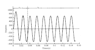
Locked rotor inrush current graph is as shown below:-

Locked rotor inrush current


Table for NEMA motors NEMA code letters for locked-rotor KVA/HP is below:-

Locked rotor current table

Let’s take an example of motor having motor rating of 30 HP and rated current of 34.9A. With code letter of G. Now lets calculate the locked rotor current of the motor.

From the table you will see that for Code letter G locked rotor range for KVA/HP is 5.6-6.3.

Now lets calculate what will be the locked rotor current for motor:-


KVA/HP X HP X1000= 1.732 X Vline X Iline

Lower range of locked rotor current will be:-
5.6 X 30 X 1000 = 1.732 X 460 X Iline
Iline = 210.8 A

Now Upper range of locked rotor current is:-
6.3 X 30 X 1000 = 1.732 X 460 X Iline
Iline = 237.2 A

So range of Locked rotor current is 210.8A to 237.2 A.

Locked rotor torque
The Locked Rotor Torque or Starting Torque is the torque the electrical motor develop when its starts at rest or zero speed.

A high Starting Torque is more important for application or machines hard to start - as positive displacement pumps, cranes etc. A lower Starting Torque can be accepted for centrifugal fans or pumps where the start load is low or close to zero.


Tuesday, June 14, 2016

Transmission tower parts and types of Transmission towers

For transmission of power at High voltage Transmission lines needed to be laid. For laying Transmission lines Transmission towers are most widely used in world. Transmission towers are used for following purposes:-
1.       To separate high voltage conductors from surroundings and from each other.
2.       To keep conductors at sufficient height for safe limits.


An overhead transmission line usually consists of three conductors or bundles of conductors containing the three phases of the power system. The conductors are usually aluminum cable steel reinforced (ACSR), which are steel core (for strength) and aluminum wires (having low resistance) wrapped around the core.

Tower designing is most important part as towers has to sustain natural calamities.  There are following parts in Transmission towers:-
1.       Tower top
2.       Cross arm
3.       Beam
4.       Insulator string
5.       Fork (K-Frame)/ Cage of Transmission tower
6.       Tower body & Leg of Transmission tower
7.       Tower base
8.       Vibration damper

Every part details will be discussed below:-
1.       Tower top:- Tower top is used to carry earth shield wire. This is connected at tip of tower also known as earth wire
2.       Cross arm:-
Cross arm is used to hold insulators. Insulators are used to carry transmission conductors. Dimensions of cross arm depends upon level of voltage to be transmitted.
3.       Beam:-
Beam is the portion between cross arms. This is used to hold cross arms.
4.       Insulator strings:-
Insulator string is used to carry transmission lines. There no. very depending upon the level of Transmission voltage to be transmitted. As the voltage level increase no. of insulators increases in a string.
5.   Cage of Transmission tower(Fork K-Frame):-
Cage is the main structure of Transmission towers which provides support to whole body of Transmission tower.
6.   Tower body and leg of Transmission tower:-
They are base of transmission tower. During design of Transmission tower minimum ground clearance of the lowest conductor point above the ground level is depends upon Tower body and leg of transmission tower. Higher the voltage to be transmitted higher will be the ground clearance required than higher will be the width between legs of Transmission towers.
7.   Tower base:-
Base of tower is the main holding of whole Transmission tower.
8.       Vibration Damper:-

As clear from its name these are used for damping out vibrations due to wind in transmission towers. If dampers are not used than conductors get fatigue from where it is hanged. There re 2 types of vibration dampers (i) VORTX/ Stock bridge Type (ii) Spiral vibration damper

Vortex/ Stock bridge type vibration dampers are most widely used.


Transmission tower height is crucial point for any Transmission tower design. Transmission towers height to be designed depending upon:-

(a)                Minimum ground clearance higher the level of voltage to be transmitted higher will be the ground clearance.  
(b)               Maximum sag of conductor. Sag is necessary evil in transmission lines, you can’t lay transmission conductors without sag.
(c)                Vertical gap between top and bottom conductors.
(d)               Gap between ground wire and top conductor.
A typical transmission tower with horizontal configuration height  is 100 feet.  These types of  towers  are designed to bear the vertical load of the conductor weight and horizontal loads from wind against the towers and the conductors.

There are following types of transmission towers:-
 a) Suspension/Tangent towers <2°
b) Small angle towers 2 ° -15 °
c) Medium angle towers 15 ° -30 °
d) Large Angle towers 30 ° -60 °
 e) Dead end towers >60 °
f) Transposition towers(4Xarms)
g) Special towers – JC, MC, NB, NBMC
h) Pole mounted termination towers
i) Mono poles


Saturday, June 11, 2016

Cables selection Methodology in electrical systems

1.       Cable Selection according to voltage level:
Cables are selected according to voltage level required to be carried by cable. Nominal voltage of the cable is usually expressed in Volts. Cables have nomenclature according to voltage level to be carried through the cables.

There are following types of cables according to voltage levels:-
Low tension cables:- Cables having voltage level upto 1000V
High tension cables:- Theses cables have voltage levels upto 11000V
Super tension Cables:- These cables having voltage level from 22KV to 33 KV
Extra High tension cables:- These cables having voltage level from 33KV to 66 KV
Extra Super voltage cables:- These cables having voltage levels beyond 132 KV
 (2) Cable selection according to Current carrying capacity of cables:
Cables are selected according to current carrying capacity of cables. This current carrying capacity is known as Ampacity. Cables are usually copper/ Aluminum cables , these cables are selected according to requirement of load connected at cable. Usually cables are selected 20% higher than the maximum current connected across cable.
Short circuit current values are also considered while selecting the cable.  Short circuit will leads to rise in temperature of cables. Cables are usually selected according to short circuit current carried by cables without much rise in temperature.
There is another factor which must be considered while selecting a power cable is voltage drop. Voltage drop depends upon resistance of power cable. Cable resistance depends upon length and diameter of cable. Cable size is selected according to voltage drop over the length of cable.


No of Cores in cable:
In electrical systems there are cables used single core to multicore cables. For Single phase power supply usually 2 core cable is used for three phase cables used are 3 core , 3.5 core or 4 core. Single core cables are used in electrical systems. 3.5 core is most widely used as 4 core cables uses neutral of same size of other cores but in 3.5 core cable neutral is half of size of other cores.
There are multicore cables such as 14 core/26 core/ 48 core etc.  these cables are used for control cables. These cables are both shielded and unshielded. Shielded cables are used for field instruments where interference from other signals to be avoided.

 Cable selection according to type of Insulation:
§  Cables are selected according to type of insulation used in cables e.g. PVC, XLPE , rubber. Usually XLPE and PVC insulated cables are used XLPE cables are cheaper than PVC cables. Cables outer sheath is designed as per standards : IS: IS:7098 / IEC:60502 / BS:6622/BS:7835.
 Cable selection according to Method of Installation:
Cables are both armored, Unarmored and flexible cables these cables are selected according to method of installation of cables.
Cables are to be selected according to method of laying of cables, there are following ways of laying the cables:-
1.     Underground
2.     Above ground in cable tray
3.     In air
If cable is to be laid underground than armored cable is used as it will provided more strength to cables.

If there is required to lay cables in cable tray than unarmored cables are used as these will leads to lower cost.
If we lay cables in air than these cable will carry higher current than the same cable laid underground.
Armoring of cable is done as per Codes: IS: 7098 / IS: 3975 / IEC:60502 / BS:6622/BS:7835.


Cable selection according to Environmental conditions:
§  Cables are usually selected according to industry and environment where these are used. E.g. XLPE cables are used where there are moisture conditions. A PVC jacket is a very stable material against a wide range of chemicals, while HDPE jacketed cables can serve better in wet locations.
       Elastomeric Cable is applied in trailing, coal cutter, wind mill, panel wiring, battery cable and such other areas.