Search This Blog

Saturday, February 8, 2014

Lighting Plan According to building

How to Develop an Acceptable Lighting Plan


1. Identify where as well as when lighting is needed. Confine and minimize lighting to the
extent necessary to meet safety purposes. Plans should define the areas for which illumination is
planned. Itemizing each area (e.g. parking lot, doorways, walkways, signage, foliage) with the
anticipated hours of use. Commercial outdoor lighting should be used for safe pedestrian passage
and property identification, and lit during active business hours and shut off afterward.

2. Direct light downward by choosing the correct type of light fixtures.
Specify IES (Illuminating Engineering Society) "Full Cut Off" designated or “fully shielded” fixtures,
so that no light is emitted above the lowest light emitting part of the fixture. Top mounted sign
lighting is recommended with "RLM" (dish) type shields, and aimed so that the light falls entirely on
the sign and is positioned so that the light source (bulb) is not visible from any point off the
property or into the roadway to reduce glare. For each one square foot of sign, usually no more
than 200 lumens is necessary for good visibility.

3. Select the correct light source (bulb type). Compact fluorescent (2300K) or High Pressure
Sodium is recommended unless the light is motion sensor activated, in which case incandescent or
the instant start compact fluorescent bulbs can be used. Metal Halide (due to its higher costs, energy
use, impact on the environment, and greater contribution to "sky glow") is discouraged, as well as
light sources rated over 3000 Kelvin; and outdated Mercury Vapor bulbs are prohibited.

4. Utilize "shut off" controls such as sensors, timers, motion detectors, etc. Automatic controls
turn off lights when not needed. All lights should be extinguished no later than one half hour after
the close of business. Additional motion sensor activated lighting can be used for emergency access.
Avoid "dusk-to-dawn" sensors without a middle of the night shut off control. Lights alone will not
serve to "protect" property and are a poor "security" device. Examine other means of protecting
property and to discourage criminal activity. Let your local police know that you have a “lights out”
policy so that they can investigate if they see lights or activity after hours.

5. Limit the height of fixtures. Locate fixtures no closer to the property line than four times the
mounting height of the fixture, and not to exceed the height of adjacent structures. (Exceptions
may be made for larger parking areas, commercial zones adjacent to highways, or for fixtures with
greater cut off shielding behind the pole mount in commercial zones.)

6. Limit light crossing property lines, i.e. “light trespass”. Limit light to spill across the property
lines. Light levels at the property line should not exceed 0.1 footcandles (fc) adjacent to business
properties, and 0.05 fc at residential property boundaries. Utility leased floodlight fixtures mounted
on public utility poles in the public right-of-way should not be used.

7. Use the correct amount of light. Light levels and uniformity ratios should not exceed
recommended values, per IESNA RP-33 or 20.  "Lumen cap" recommendations for areas to be illuminated are as follows:commercial properties in non-urban commercial zones = 25,000 lumens per acre; for projects in residential and LBO zones = 10,000 lumens per acre. For residential properties: for suburban:
50,000 lumens per acre cap, and in urban areas: 100,000.

8. Ask for Assistance Your Planning Department and local lighting sales representatives can assist
you in obtaining the necessary information for good lighting. For large projects over 15,000
lumens: greater energy conservation and control of light pollution, light trespass and glare, may be
achieved with the help of a professional lighting designer with "dark sky" lighting plan experience.

9. A post installation inspection should be conducted to check for compliance. Substitutions
by electricians and contractors are common and should not be accepted. Final Approved Site Plans
will not allow additional exterior fixtures or substitutes without reviews.

10. Design interior lighting so that it does not illuminate the outdoors. Provide interior lighting
photometrics for the building’s perimeter areas, demonstrating that the interior lighting falls
substantially within the building and not through the windows. After closing, interior lighting
that extends outdoors needs to be extinguished by the use of shut off timers.

Thursday, February 6, 2014

Calculate Numbers of Pipe Earthing

Earthing is very important aspect for both Domestic and industrial applications. But there is always need to know how many earthings are required for connecting the system , below and above that mark could not serve the required purpose. 


Below is given the formula for calculating no. of earthings required for the system.

Calculate Numbers of Pipe Earthing:

Earthing Resistance & No of Rod for Isolated Earth Pit (Without Buried Earthing Strip):

  • The Earth Resistance of Single Rod or Pipe electrode is calculated as per BS 7430:
  • R=ρ/2×3.14xL (loge (8xL/d)-1)

  • Where ρ=Resistivity of Soil (Ω Meter),
  • L=Length of Electrode (Meter),
  • D=Diameter of Electrode (Meter)
  • Example:
  • Calculate Isolated Earthing Rod Resistance. The Earthing Rod is 4 Meter Long and having 12.2mm Diameter, Soil Resistivity 500 Ω Meter.
  • R=500/ (2×3.14×4) x (Loge (8×4/0.0125)-1) =156.19 Ω.
  • The Earth Resistance of Single Rod or Pipe electrode is calculated as per IS 3040:
  • R=100xρ/2×3.14xL (loge(4xL/d))

  • Where ρ=Resistivity of Soil (Ω Meter),
  • L=Length of Electrode (cm),
  • D=Diameter of Electrode (cm)
  • Example:
  • Calculate Number of CI Earthing Pipe of 100mm diameter, 3 Meter length. System has Fault current 50KA for 1 Sec and Soil Resistivity is 72.44 Ω-Meters.
  • Current Density At The Surface of Earth Electrode (As per IS 3043):
  • Max. Allowable Current Density  I = 7.57×1000/(√ρxt) A/m2
  • Max. Allowable Current Density  = 7.57×1000/(√72.44X1)=889.419 A/m2
  • Surface area of one 100mm dia. 3 meter Pipe= 2 x 3.14 x r x L=2 x 3.14 x 0.05 x3 = 0.942 m2
  • Max. current dissipated by one Earthing Pipe = Current Density x Surface area of electrode
  • Max. current dissipated by one Earthing Pipe = 889.419x 0.942 = 837.83 A say 838 Amps
  • Number of Earthing Pipe required =Fault Current / Max.current dissipated by one Earthing Pipe.
  • Number of Earthing Pipe required= 50000/838 =59.66 Say 60 No’s.
  • Total Number of Earthing Pipe required = 60 No’s.
  • Resistance of Earthing Pipe (Isolated) R=100xρ/2×3.14xLx(loge (4XL/d))
  • Resistance of Earthing Pipe (Isolated) R=100×72.44/2×3.14x300x(loge (4X300/10))=7.99 Ω/Pipe
  • Overall resistance of 60 No of Earthing Pipe=7.99/60=0.133 Ω.

Friday, January 31, 2014

Calculation for Min. Cross section for Earthing conductor at particular fault level

Calculate Min. Cross Section area of Earthing Conductor

Cross Section Area of Earthing Conductor As per IS 3043 (A) =(If x√t) / K

Where: t = Fault current Time (Second).
 K = Material Constant.

 Example:
Calculate Cross Section Area of GI Earthing Conductor for System has 50KA Fault Current for 1 second. Corrosion will be 1.0 % Per Year and No of Year for Replacement is 20 Years.

 Cross Section Area of Earthing Conductor (A) =(If x√t) / K

Here: If = 50000 Amp
T = 1 Second
 K = 80 (Material Constant, For GI=80, copper K=205, Aluminium K=126).

Cross Section Area of Earthing Conductor (A) = (50000×1)/80
Cross Section Area of GI Earthing Conductor (A) = 625 Sq.mm

Allowance for Corrosion = 1.0 % Per Year & Number of Year before replacement say = 20 Years

 Total allowance = 20 x 1.0% = 20%
Safety factor = 1.5 Required Earthing Conductor size = Cross sectional area x Total allowance x Safety factor Required Earthing Conductor size = 1125 Sq.mm say 1200 Sq.mm

Hence, Considered 1Nox12x100 mm GI Strip or 2Nox6 x 100 mm GI Strips

Tuesday, October 15, 2013

Faults in Electrical Lighting system and Most Severe Fault in lights

We often observe day to electrical faults in our appliances such as 
1.Tube rod get faulty 
2. Lights not working 
these are all happens due to Aging of equipment's

Below are the faults which are not in control:-

1. High voltage from source
2. Low voltage from source
these types of abnormalities usually effect electronic equipment's such as TV, fridge, Microwave etc. 
So to avoid faults in these equipment's usually Stabilizers are installed for them. So that any abnormality in source voltage could not effect our load end. 

But severe fault occurred when neutral get breaker from transformer in that case in that case Neutral becomes a floating neutral and phase starts coming in Neutral. Which causes burning of every equipment and even may cause fire if lights not switched off in line. 

Now Question arises How voltage starts coming in Neutral?
Answer for the same is that During neutral break if Transformer load is balanced then lights and equipment doesn't burn. But whenever any load get switched off particular phase that unbalance voltage causes burning of equipment's. so it is always advised to earth the neutral at load end also. So that even if neutral break from Transformer load end earthing of neutral saves burning of equipment's. If there are still doubts then Please ask

Monday, October 14, 2013

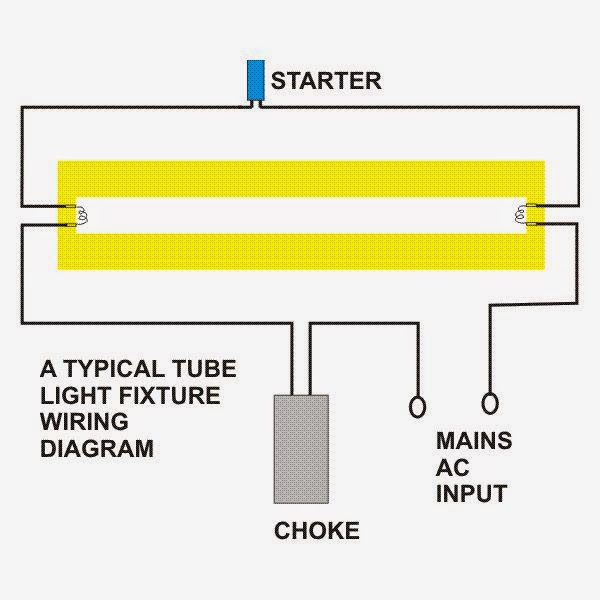
Working principle of Choke; Specifications of Choke

Choke is very important of Tube light. Usually tube light doesn't work without choke.

Working: 

Normal operating voltage of tube light is about 110 but naturally available voltage is 240 V in India hence the choke comes into picture which gives 110 V output.

But for initiating the light (to ionize the gas in the tube) the system, system requires 800 - 1000 V to provide this starter has been used, which block the current flowing from the choke to light hence the voltage will build up across the load. once the maximum voltage reached which starter can withstand, the starter closes the circuit and the build up voltage applied across tube light.

Principle:-
Choke is actually an Inductor As we know inductor opposes the rate of change of current here we are making current I which is intially drawn to zero with the help of bimetallic contacts present in starter

According to formulae E=L*di/dt here L is constant and di is equal to I-0 and dt is time taken for I to become zero Accordingly high voltage is induced and this voltage is sufficient to drive the electrons from one electrode to another electrode inspite of medium present between electrodes.

Once conduction starts there after choke just provide voltage which is sufficient for conduction i.e. 110V.

Choke is shown in Tube light circuit as:-

Choke functions in Tube light


 Thus Choke performs two functions:-
 1. Provide high voltage during starting for ionization of Gas
 2. Provide low voltage for continuous working of tube light.

There are two types of chokes available in the Market:- 

1. Copper choke.
2. Electronic choke.

A copper choke usually has following specifications:-

 For single tube light  current taken by choke is 0.39 A and Power factor of 0.5 only with Delta T of 70 and an Electronic choke Power factor ranges between 0.8 to 0.9.

 Electronic chokes are thus now most widely used as PF is very high so current drawn will be low. Also losses in copper choke are high then electronic choke also there is no light flickering occurs while starting electronic choke tube in comparison to Copper choke.

Light Color Temperature; Applications of Different color Tempratures

This is the color of the light as perceived by the human eye.

It is measured in degrees Kelvin (°K) •

The general terms used for artificial light colors are:

Warm White -- 3000 K
Cool White   -- 4100 K
Daylight       -- 6500 K – This is what our bulbs & tubes are

Detailed application of Different color temperature:-

5000- 8000 K -- Daylight White for Petrol Pumps & Winter good shops
4000-5000 K  -- Cool White for Offices, Hospital, industries
3500-4000 K  -- Super Stores, Showrooms
2700-3000 K -- Warm White For Residential Lights, Restaurants
2000-2500 K -- Extra Warm for Display, Street lights

Sunday, October 13, 2013

Multimeter, Earthing, Megger, Motors fundamentals

Lets continue with Fundamentals of Electrical Engineering:-

1. Whenever checking electricity supply in Industry then keep assured with Multimeter as sometimes line tester may get failed and will not function and also Line tester even starts glowing at 5 V only.

2. Megger should be used to check motor winding resistance, Insulation of motor Multimeter may not always gives correct data.

3. In an Industry grid should be formed for Earth pits. As in grid all earth pits resistance comes in parallel with each other which will ultimately resistance of grid. Whenever earth fault occurred then fault current will go through grid as Grid offers lesser resistance.

4. Separate grids should be formed for Electrical and Electronic pits.

5. Double earthing of electrical system is required where there was there phase system is used and single earthing is sufficient in case of single phase system.

6. Electricity is not flow of electrons it's the vibration of electrons.

7. 3-Phase Motor direction can be changed by interchanging two phases.

8. Capacitor banks supplies reactive power and it doesn't consumes active power.

9. Capacitor banks Rating is in KVAR i.e. Volatage X Current X Sine angle.

10. Earth pit tester is used for measurement of earth resistance.