Search This Blog

Saturday, October 3, 2015

International and Indian Standards for Transformers

During Transformer Manufacturing there are following codes and standards which manufacturer must comply for better performance and safety aspects:-
For Transformer specifications visit link as below:-

http://electrialstandards.blogspot.com/2015/10/transformer-technical-specifications.html

For Transformers applicable Codes, Standards, rules, Acts:-
Standard and Rule
Description of Standard, Rule
IEC: 60616
Terminal and Tapping Marking for Power Transformers
IEC: 60529
Degrees of protection provided by Enclosures (IP Code)
IEC: 60905
Loading guide for Dry-type power transformers
IEC:60044
Instrument Transformers- Current and voltage transformers
IEC:60225
Electrical relays
IEC:60625
High voltage switches
IEC:62271-202
High voltage switchgear and control gear-Prefebricated Substation
IS:335
Insulating oil
IS:1271
Thermal evaluation and classification of electrical insulation
IS:2099
Bushing for Alternating voltage above 1000V
IS:2705
Current Transformers
IS:3347
Dimensions for Porcelain Transformer bushing
IS:3637
Gas operated relays
IS:3639
Fitting & Accessories for power transformers
IS:3156
Voltage Transformers
IS:4201
Application guide for CT’s
IS:6600
Guide for loading of oil immersed transformers
IS:2629
Recommended practice for Hot-dip galvanizing of iron and steel
IS:8478
Application guide for On-load tap changer
IS:8468
On-load tap changer
IS:10028
Code of practice for selection, installation & maintenance of transformers
IS:13947
LV switchgear and Controlgear-Part1
IS 2026
Power Transformers
IS 1180
Outdoor type oil immersed distribution transformer up to and including 2.5MVA,33kV
IS:7098
XLPE cables
IS 5561
Electrical Power Connectors
IS 5
Colors for ready mix paints
IS: 11171
Dry type Power Transformer

Indian Electricity Rules

Indian Electricity Act

CBIP manual


You have seen that there as so many standards both international and Indian standards. During purchasing the Transformer if any one doesn't know Transformer specifications than just go through these Indian standards and they will get enough knowledge about Transformers manufacturing, testing, everything about transformers.

These Indian standards are freely available on internet.


Friday, October 2, 2015

Transformer Oil Filtration process; Complete guide to Transformer oil filtration

Transformer oil get contaminated during process. During usage transformer oil absorbs moisture, dirty particles. Which needed to be removed from transformer oil as Transformer oil efficiency get reduced due to moisture and other contaminations.
Transformer oil filtration process is used to remove the moisture from oil so to dehydrate the oil and remove unwanted solid particles.
 Also degassing is done in transformer so to maintain transformer oil level.

For Transformer technical specifications visit link:-
http://electrialstandards.blogspot.com/2015/10/transformer-technical-specifications.html
Oil filtration enhances transformer life.

Advantages of Transformer oil filtration
Below are the listed some advantages of transformer oil filtration:-
1.       Oil filtration will improve better insulation of Transformer winding as Transformer oil is used for both transformer cooling as well as insulation.
2.       Oil filtration will improve insulating media such as Paper, cellulose used in transformer.
3.       Oil filtration increase life if transformer as 70% transformer breakdown occurs due to transformer oil contamination.
If Transformer oil filtration doesn’t done then following problems may occur in transformers:-

1.       Overheating of transformer oil and may leads to burning of Transformer.
2.       Corona discharges in Transformer
3.       Arcing in Transformers
So it is always important to maintain transformer oil Dielectric Strength.
There are three processes for Transformer oil Treatment:-

1.       Purification
2.       Filtration
3.       Degassing and dehydration

1.       Purification:-
In first step Transformer oil temperature is raises to raised to 65 degree Celsius. At this temperature moisture and gases get separated from oil in degassing chamber. At this temperature viscosity of Transformer oil drops which will leads to better filtration.

2.       Filtration:-
In this process sludge and dirt are removed from Transformer oil. There are two methods for removing the sludge and dirt from Transformer oil, these are:-
(i)                   Removal of Sludge and dirt by using filter candles and
(ii)                 Removal of Sludge and dirt by means centrifugal action.
Now let’s discuss about these two methods:-
(i)                   Removal of Sludge and dirt by using filter candles
In this method of filtration , filtration can be done by two methods:-
(a)     By using edge filter known as classical edge filter method
(b)      By using depth filter method also known as filter cartridge method
(a)     In edge filtration method has following advantages:-

1.       Filter can be cleaned and reused for several times.
2.       It can handle large quantity of sludge
Disadvantages of edge filtration method:-
1.       Cleaning of edge filter requires lot of time and effort.
2.       Reinstallation of edge filter requires lot of time and effort.
In edge filtration, filter is cleaned by using reverse pressurized flow of dry air or nitrogen. After cleaning it is dried in bright sunlight. Reinstallation, cleaning, drying is effort taking and time consuming and also required special skills for the same.
(b)     Filter cartridge method:-
Now days this method is used and cartridges used in this method are very much similar to those of the water filter cartridges. There are so many verities of purification ranges depending upon cartridge openings i.e. from 500 micron to 0.5 micron size.
 There are certain advantages of using filter cartridges over edge filtration method:-
(i)       Ease of replacement
(ii)     Ease of availability
(iii)    No moisture as filter used is non-hygroscopic but edge filtration method filters are hygroscopic.

(ii)                Centrifuging action for removal of sludge.
 Centrifugal action as everyone knows that in centrifugal action heavy particles automatically get accumulated at bottom by centrifugal force and liquid from which particles to be removed is get separated. In Transformer oil cleaning Centrifuges are used in shape of cone which are used to separate sludge and particles from Transformer oil. It is very slow process if we don’t use motor to spin centrifuge cone at high speed. By this method we can’t able to remove dirt which have sizes less than 10 micron level.
To remove this limitation of centrifugal action a power driven centrifuge is uses. Although it is very costly method but it has main advantage is that it doesn’t require changing of filter elements. There is one limitation of this method is that it can remove un-dissolved water from the oil but it can’t remove dissolved moisture from oil.

3.       Degassing and Dehydration of Transformer oil 
In last step of Transformer Oil filtration dehydration and degasification of oil is done. This process takes place in degassing chamber. This process is possible in vacuum as there is difference in boiling point of water, gas and Transformer oil. In gas separation process it is very important to retain the ar hydrocarbons so as to retain oil properties. Water is removed by either centrifugal action or by usinf coalescing action.


This is how oil filtration takes place in Transformer oil. 

Saturday, September 12, 2015

Short circuit test on Transformers;Why Short circuit test performed on HT side

As we have seen in open circuit test that it is done on low voltage winding. Short circuit test is done of High voltage winding. In this case Ammeter, Voltmeter, Wattmeter are connected on High voltage winding of the transformer. This test is done to calculate copper losses in Transformer at full load. This test is performed on HT side not on LT side as Short circuit test in Transformer is conducted at its rated current which can be easily obtained by applying 5-6% of normal voltage.


If we conduct Short circuit test on LT side by short circuiting HT side then Voltage of HT winding falls to zero which leads to very high current on High voltage winding leading to burning out of winding.

For no load test on Transformers visit link:-
http://electrialstandards.blogspot.in/2015/09/no-load-test-on-transformers-open.html


Now lets take a Example if we have Transformer 2 MVA, 415V/11000V then 
if we perform Short circuit in LT side the current will be:-

2     X      10^6 =   2782A
1.732 X 415

Now if short circuit test is done on HT side then rated current will be:-
2     X      10^6 =   104A
1.732 X 11000

Now you will see how much the difference in rated currents.


Also Since short circuit test is done at rated current so it can be easily obtained in HT side then on LT side as rated current value is low on HT side instead of LT side as there the difference equal to Transformation ratio.

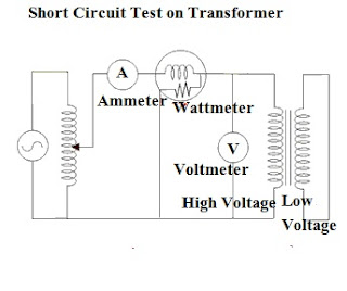
Connection diagram for performing Short circuit test on Transformer in as Shown in figure below:-


Short circuit test on Transformer

With the help of Variac voltage is applied and increased slowly until the ammeter on HT side read the rated current. Now readings of all the connected instruments are recorded. The ammeter reads the full load current of primary side which will be If. As voltage applied for achieving this full load current will be very small core losses can be ignored. Now wattmeter connected on HT side will give copper losses. Now let’s assume wattmeter reading is Ps.c. and Voltmeter reading as Vs.c. then


Ps.c.= If2 R

Where R is equivalent resistance.

Saturday, September 5, 2015

No load Test on Transformers; Open Circuit test on Transformers

Open Circuit Or No Load Test on Transformer
Open circuit test is also known as no load test. This test is performed on Transformer to calculate core losses at no load.


As indicated by name Open circuit means transformer one winding is kept. So usually High voltage side is kept open as at load voltage and current readings are very low which could not be feasible to measure on high voltage side. So in this test High voltage winding is kept open and Voltmeter, Ammeter, Wattmeter are connected on Low voltage side and source of supply is also connected on Low voltage side for measurement of parameter.

For short circuit test on Transformers visit:-
http://electrialstandards.blogspot.in/2015/09/short-circuit-test-on-transformerswhy.html

Connection diagram for the same is as shown below:-
In open circuit test as discussed earlier that this test is performed on low voltage side so all measuring instruments are connected on low voltage side i.e. A voltmeter, wattmeter, and an ammeter are connected in LV side of the transformer as shown.
Low voltage is applied to that LV side through a variac. The High voltage side of the transformer is kept open.  This applied voltage is increased till the rated voltage of low voltage winding. Readings of the measuring instruments are recorded.


Ammeter gives the no load current which is usually very small in comparison to rated current of transformer so losses due to that current will be very small and can be ignored i.e. copper losses can be ignored. Now as voltmeter gives the rated voltage and wattmeter connected in low voltage winding gives Input power without load at secondary side. As secondary winding is open circuited so wattmeter gives core losses of the transformer.

No load Test on Transformer


So Open circuit test gives core losses of the transformer. Let’s consider that power indicated by wattmeter was P(o) and voltmeter reading as V(o).

Then P(o)= V(o)2
                    Rm
Rm is the shunt resistance of the transformer.

Thus we have seen that Open circuit test will give Core losses of the transformer.

Saturday, August 22, 2015

Silica gel breather in transformers; Silica gel breather functions

Every electrical engineer have seen silica gel in Transformer. This article is wholly based on Silica gel.
Why Silica gel required in Transformer?
What are functions of Silica gel in Transformer?
When to change the silica gel?


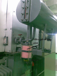
In transformers Silica gel portion is referred as Silica gel breather. It is usually connected to conservator tank through a breathing pipe.


Silica gel breather mounting in Transformer

Whenever transformer is loaded i.e. near to full load, temperature of the Transformer oil get increased which leads to expansion of transformer oil means volume of oil get increased. Now when Volume of oil get increased air trapped above oil  level in conservator tank comes out.

Now when transformer is lightly loaded transformer oil cools down which will leads to decrease in transformer oil volume. Which will leads to air from surroundings get enter above conservator oil level, now this air contains moisture which must be needed to removed otherwise it will leads to moisture getting mixed with oil. If this moisture get mixed with oil than that will be very harmful for transformer Insulation. To remove this moisture silica gel is used. Silica gel absorbs this moisture and doesn’t allow moisture gets enter into transformer.
As during this process air leaves and enters the transformer that is why this is knows as silica gel breather. Which means transformer is breathing.

Silica gel breather in Transformers


Silica Gel color and changing silica gel period

Silica gel is blue in color but when it starts absorbing moisture it starts get pink in color. There is not defined life of silica gel , When 50% of silica gel turned into pink means there is need to change the silica gel.

Functions of Silica gel breather
Silica gel breather construction is very simple it just contains a pot filled with blue silica.
1.     Silica gel absorbs moisture form air entering the Transformer
2.     It also contains an oil pot below the silica gel pot. Oil is used to trap the dust particles in air. The oil in the oil sealing cup acts as barrier between silica gel crystal and air when there is no flow of air through silica gel breather.